


Basic electrical machines
An electrical machine can be defined as an apparatus that can be used either to convert electrical energy into mechanical energy or to convert mechanical energy into electrical energy.
If such a machine is used to convert electrical energy into mechanical energy, it is called a motor; if it is used to convert mechanical energy into electrical energy, it is called a generator.
Depending on whether such a machine functions as a generator or a motor, the moving part that is attached to a mechanical system receives mechanical input or provides mechanical output.
Rotating electrical machines have an outside (i.e. stationary) part that is called the stator and an inner (i.e. rotating) part that is called the rotor. The rotor is centered within the stator, and the space that is located between the outside of the rotor and the inside of the stator is called the air gap. The rotor is supported by a steel rod that is called a shaft. In turn, the shaft is supported by bearings so that the rotor can turn freely. Both the rotor and the stator of a rotating machine, as well as a transformer, have windings.
Magnetic fields are the fundamental mechanism by which energy is converted from one form to another in motors, generators and transformers.
Four basic principles describe how magnetic fields are used in these devices:
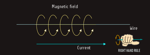
1. A current-carrying wire produces a magnetic field in the area around it.
2. A time-changing magnetic field induces a voltage in a coil of wire if it passes through that coil. (This is the basis of transformer action.)
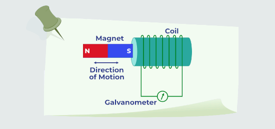
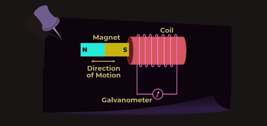
3. A moving wire in the presence of a magnetic field has a voltage induced in it. (This is the basis of generator action.)
4. A current-carrying wire in the presence of a magnetic field has a force induced on it. (This is the basis of motor action.)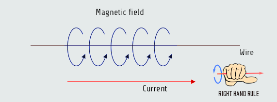
 A motor and generator perform opposite functions, but their fundamental structure is the same. Their structure is a coil mounted on an axel within a magnetic field.
Basis of transformer action
Faraday's law states that if a flux passes through a turn of a coil of wire, a voltage will be induced in the turn of wire that is directly proportional to the rate of change in the flux with respect to time.
einduced = -N dΦ/dt
e - induced voltage at coil terminal
N - number of turns of wire in a coil
Φ - flux passing through the coil
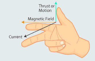
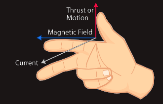
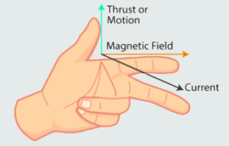
The minus sign in the equation is an expression of Lenz's law. Lenz’s law of electromagnetic induction states that the direction of the current induced in a conductor by a changing magnetic field (as per Faraday’s law of electromagnetic induction) is such that the magnetic field created by the induced current opposes the initial changing magnetic field which produced it. The direction of this current flow is given by Fleming’s right hand rule.
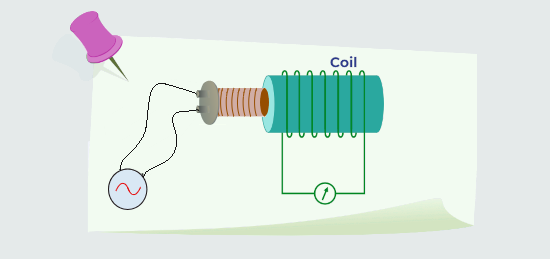
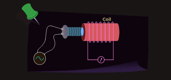
Instead of the moving magnet, if a time varying current is passed through a coil, a time-changing flux is produced which when transferred to another coil, induces a voltage across its terminals. This is the basis of the transformer action which transforms the voltage level according to the number of turns in each coil.
Basis of generator action
A wire, moving through a magnetic field, has a voltage induced in it. If the wire circuit is closed, a current is induced with a direction determined according to Fleming’s right hand rule. This is basis of generator action (mechanical energy + magnetic field → electrical energy).
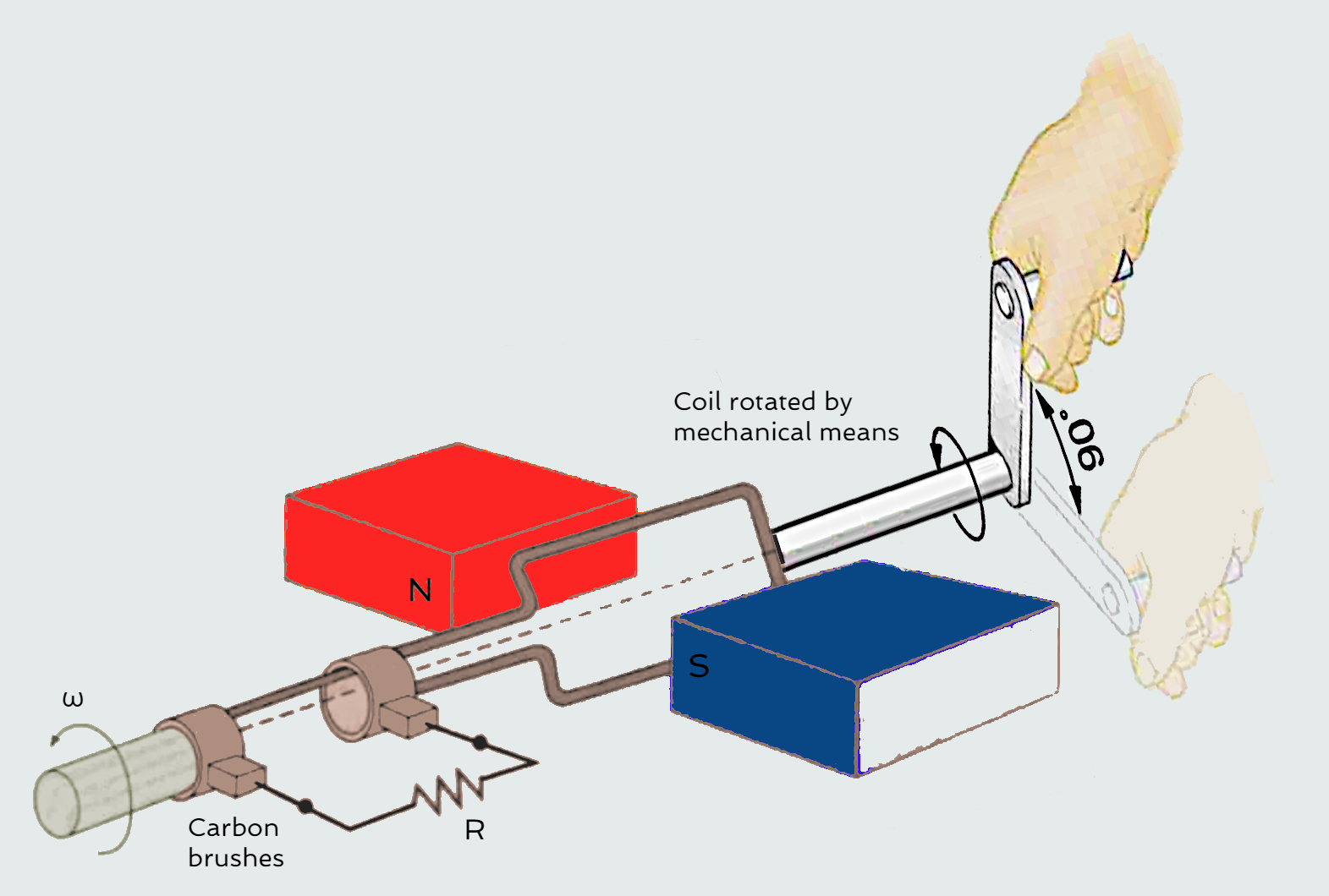
The generator is used to produce an electric current from rotational motion (on large scale power stations a turbine is used to provide this rotation). In a generator the rotation causes the coil to rotate inside the magnetic field. A rotating magnet serves as the rotor, turning within a set of conductor coils on an iron core, which serves as the stator. As the magnetic field rotates, it generates an ac voltage in the stator. The magnetic field can be created either by permanent magnets or by a field coil electromagnet. In power stations it is usually the magnet (electromagnet) which is attached to the axel and rotated, with the coils surrounding the magnet. The excitation system on an AC alternator refers to the way the alternator's voltage is initially built when rotated and controlled while in use. The excitation system is responsible for supplying the field current to the main rotor. Without the excitation system the AC alternator would have no way of building its voltage as it starts to rotate, nor would be able to regulate its voltage to the pre-set nominal level while running at its rated speed.
Basis of motor action
A force is induced on a current-carrying wire placed within a magnetic field. The direction of the force is given by Fleming’s left-hand rule. An electric motor is used to produce rotational motion from an electrical supply. In a motor an electric current is passed through the coil. The coil then creates a magnetic field that interacts with the already existing magnetic field. This interaction forces the coil to rotate.
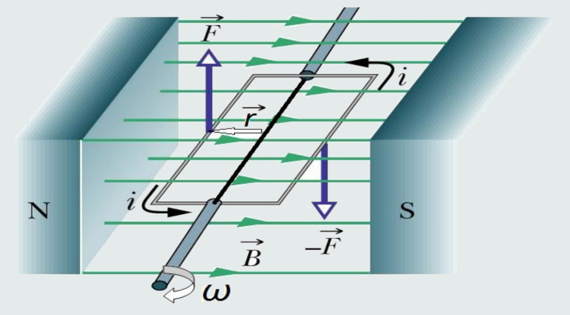
If a current carrying loop is placed in a magnetic field, a torque is produced which causes a rotational movement of the loop, which is the basis of motor action (electrical energy + magnetic field → mechanical energy). The torque on an object is defined as the product of the force applied to the object and the distance from object's axis of rotation to the line of action of the force.
T = r x F [Nm]
The magnetic field of the magnets interferes with that produced due to electric current flowing in the conductor. Since the loop has become a magnet (it is previously connected to some source of electricity, e.g. battery terminals), one side of it will be attracted to the north pole of the magnet and the other to the south pole. This causes the loop to rotate continuously.