


Oscillators
Oscillators are important in many different types of electronic equipment. For example, a quartz watch uses a quartz oscillator to keep track of what time it is. An AM radio transmitter uses an oscillator to create the carrier wave for the station, and an AM radio receiver uses a special form of oscillator called a resonator to tune in a station. There are oscillators in computers, metal detectors and so on. To understand how electronic oscillators work, it is helpful to look at examples from the physical world.
One of the most commonly used oscillators is the pendulum of a clock. If we push on a pendulum to start it swinging, it will oscillate at some frequency -- it will swing back and forth a certain number of times per second. The length of the pendulum is the main thing that controls the frequency.
For something to oscillate, energy needs to move back and forth between two forms. For example, in a pendulum, energy moves between potential energy and kinetic energy. When the pendulum is at one end of its travel, its energy is all potential energy and it is ready to fall. When the pendulum is in the middle of its cycle, all of its potential energy turns into kinetic energy and the pendulum is moving as fast as it can. As the pendulum moves toward the other end of its swing, all the kinetic energy turns back into potential energy. This movement of energy between the two forms is what causes the oscillation. Eventually, any physical oscillator stops moving because of friction. To keep it going, we have to add a little bit of energy on each cycle. In a pendulum clock, the energy that keeps the pendulum moving comes from the spring. The pendulum gets a little push on each stroke to make up for the energy it loses to friction.
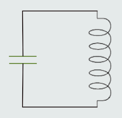
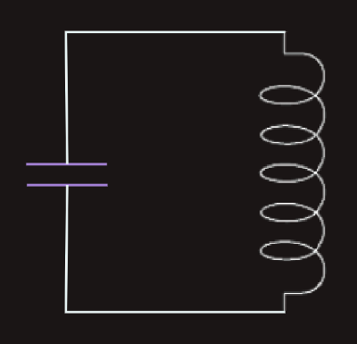
Energy needs to move back and forth from one form to another for an oscillator to work. We can make a very simple oscillator by connecting a capacitor and an inductor together. We already know that both capacitors and inductors store energy. A capacitor stores energy in the form of an electrostatic field, while an inductor uses a magnetic field.
If we charge up the capacitor with a battery and then insert the inductor into the circuit, here's what will happen:
The capacitor will start to discharge through the inductor. As it does, the inductor will create a magnetic field. Once the capacitor discharges, the inductor will try to keep the current in the circuit moving, so it will charge up the other plate of the capacitor. Once the inductor's field collapses, the capacitor has been recharged (but with the opposite polarity), so it discharges again through the inductor. This oscillation will continue until the circuit runs out of energy due to resistance in the wire. It will oscillate at a frequency that depends on the size of the inductor and the capacitor.
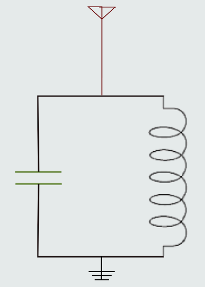
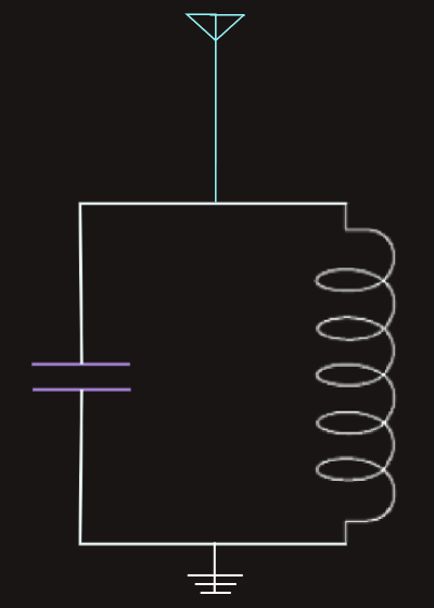
In a simple crystal radio, a capacitor/inductor oscillator acts as the tuner for the radio. It is connected to an antenna and ground. Thousands of sine waves from different radio stations hit the antenna. The capacitor and inductor want to resonate at one particular frequency. The sine wave that matches that particular frequency will get amplified by the resonator, and all of the other frequencies will be ignored. In a radio, either the capacitor or the inductor in the resonator is adjustable. When we turn the tuner knob on the radio, we are adjusting, for example, a variable capacitor. Varying the capacitor changes the resonant frequency of the resonator and therefore changes the frequency of the sine wave that the resonator amplifies. This is how we "tune in" different stations on the radio.
Inductor Basics
An inductor is a coil of wire that creates a magnetic field when an electric current flows through it. The magnetic field stores energy and can be used to create a current in a circuit.
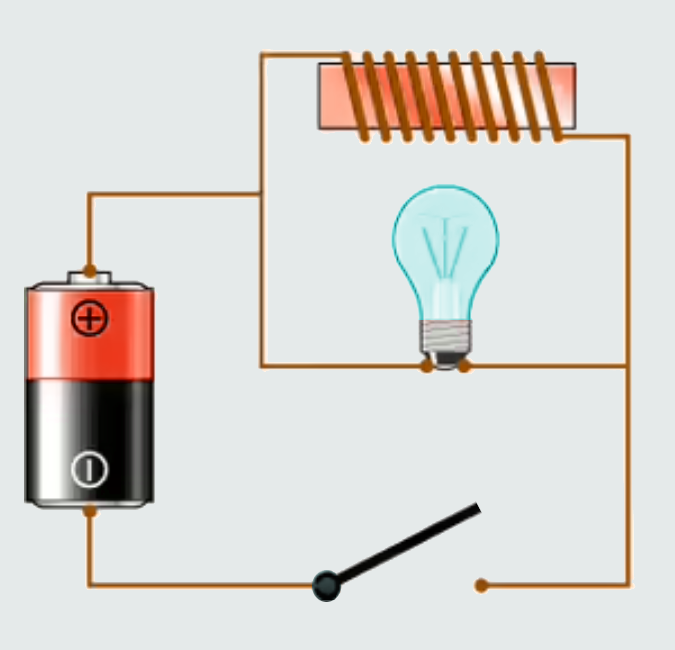
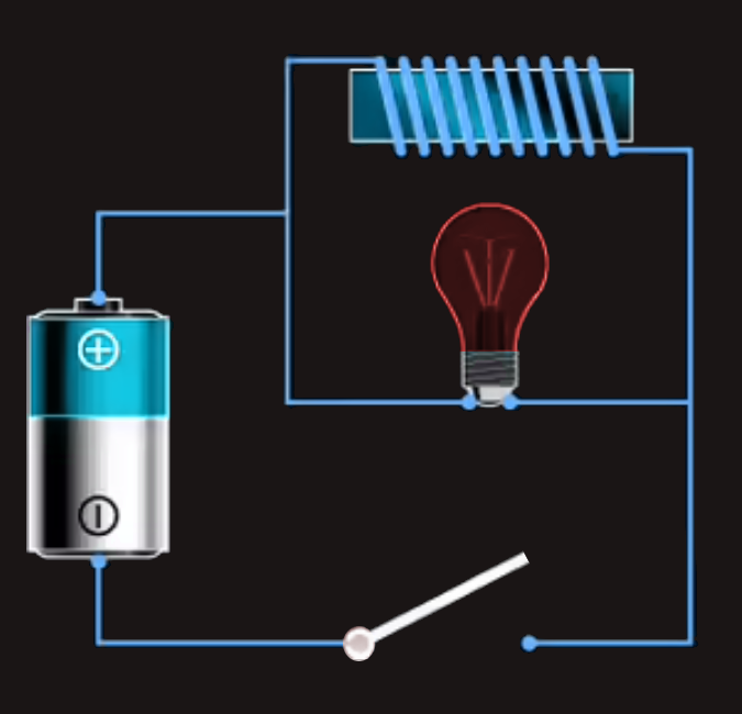
What we see here is a battery, a light bulb, a coil of wire around a piece of iron and a switch. The coil of wire is an inductor. Putting iron in the core of an inductor gives it much more inductance than air or any non-magnetic core would. If we were to take the inductor out of this circuit, what we would have is a normal flashlight. We close the switch and the bulb lights up. With the inductor in the circuit as shown, the behavior is completely different.
The light bulb is a resistor (the resistance creates heat to make the filament in the bulb glow). The wire in the coil has much lower resistance, so what we would expect when we turn on the switch is for the bulb to glow very dimly. Most of the current should follow the low-resistance path through the loop. What happens instead is that when we close the switch, the bulb burns brightly and then gets dimmer. When we open the switch, the bulb burns very brightly and then quickly goes out.
The reason for this strange behavior is the inductor. When current first starts flowing in the coil, the coil wants to build up a magnetic field. While the field is building, the coil inhibits the flow of current. Once the field is built, current can flow normally through the wire. When the switch gets opened, the magnetic field around the coil keeps current flowing in the coil until the field collapses. This current keeps the bulb lit for a period of time even though the switch is open. In other words, an inductor can store energy in its magnetic field, and an inductor tends to resist any change in the amount of current flowing through it.
Capacitor Basics
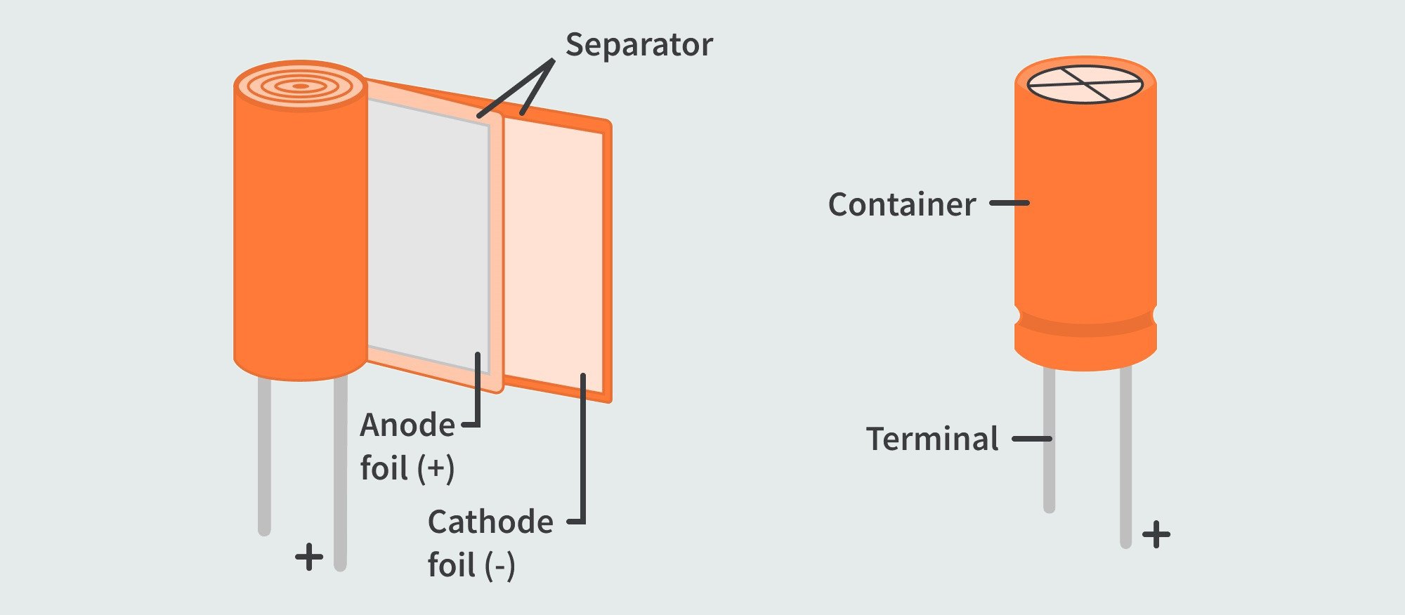
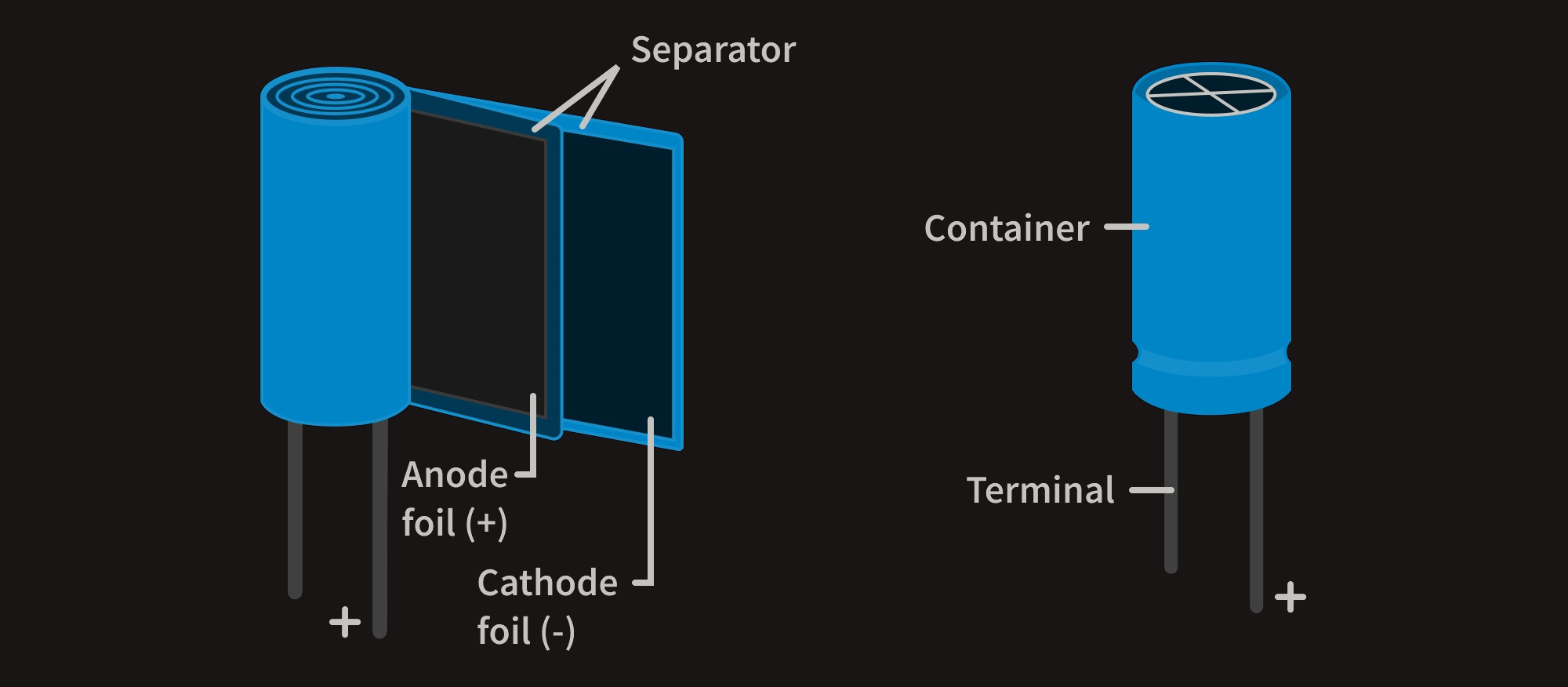
Let's say we have a battery, a light bulb and a capacitor. If the capacitor is pretty big, what we will notice is that, when we connect the battery, the light bulb will light up as current flows from the battery to the capacitor to charge it up. The bulb will get progressively dimmer and finally go out once the capacitor reaches its capacity. If we then remove the battery and replace it with a wire, current will flow from one plate of the capacitor to the other. The bulb will light initially and then dim as the capacitor discharges, until it is completely out.
This rapid release is what powers our camera's flash, gives a kick-start to our car's engine, or even regulates the electricity flow in a power grid.
Actuators and their applications
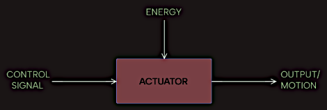
The actuator does what the controller tells it to do. An actuator is simply a mover. It can move, carry, or perform other similar functions just like the hand in human. It requires a control signal from a controller to carry out its actions. The control signal is the result of the processing done by the controller through the program (a set of instructions) written into it.
Hence an actuator is a device or component that produces an action or motion. It can be referred to as a mover because it moves to control a system. It usually requires a control signal from a controller and an energy source, which can be electric, pneumatic (air), or hydraulic (liquid). When it receives a control signal, it converts its own energy (electric, pneumatic, or hydraulic) to a form of energy or motion that can perform the required action. 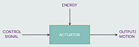
 One major application of an actuator in industry is the opening and closing of valves. In situations where manual actuation of a valve to open or close it is not realistic, such as remote locations or on very large valves, a pneumatic, electric, or hydraulic actuator is required. The actuator (electric, pneumatic, or hydraulic) provides the power or motion required to open or close the valve by converting its own energy to a mechanical force (or motion) when it receives a control signal from a controller.
The motion produced by an actuator can either be linear or rotational.
Electric actuators
Electric actuators are used in industry to convert electrical energy to kinetic energy to cause the movement of loads or perform actions that required motion or force. The operation of most electric actuators is based on the interaction between a magnetic field and a current carrying conductor to create a turning force. They utilize electric motors to perform the necessary action. An electric actuator can be referred to as a device that converts electrical energy into a linear or circular motion, hence we have electric linear actuator and electric rotary actuator.
First one is an actuator that will move in a linear direction.
Electric rotary actuators are commonly used in automation systems. Examples include direct current (DC) motors, AC motors, stepper motors, and servo motors.
Direct current (DC) motors convert electrical energy (through DC) to mechanical energy (motion). A DC motor consists of a stator, an armature, split ring commutators, and brushes. The stator is the stationary part, which usually consists of permanent magnets, and the armature is the rotating part, consisting of a coil of wire. The windings of the coil are connected to split ring commutators. The split-ring commutators ensure the direction of the current in the coil is reversed each half turn. When a current is passed to the coil through the brushes and split ring commutators, a rotating magnetic field is created that interacts with the differing fields of the magnets in the stator to create a turning force (torque), which causes the armature (coil) to rotate.
Alternating current (AC) motors convert electrical energy (through AC) to mechanical energy (motion). Unlike a DC motor, which makes use of DC as its energy source, an AC motor uses AC as its energy source. AC motors generally consist of two main parts, which are the stator and rotor. The stator is a stationary part with coils supplied with AC. The flow of the AC in the stator coil creates a rotating magnetic field. The rotor is the rotating part and is attached to an output shaft. The rotor also produces its own rotating magnetic field through the induced current from the stator or other means. The interaction between the rotating magnetic field of the stator and the field of the rotor creates a turning force that causes rotation. An AC motor can be single-phase or three-phase. A single-phase AC motor uses a single-phase supply (live and neutral) while a three-phase AC motor uses a three-phase supply.
A stepper motor is a type of DC motor that rotates in steps. It does not turn arbitrarily when its terminal is connected to a source, rather it turns in steps. It also consists of a stator and a rotor. The stator consists of windings (coils) while the rotor is usually made of a permanent magnet. Activating the windings of the stator step by step in a particular order will create a turning force as the electromagnetic poles of the stator winding react with the poles of the permanent magnet of the rotor.
A servo motor is a rotary actuator that can rotate with high efficiency and great precision. It is good for rotating objects at some specific angle or distance. They are commonly used in robotics and automation technology. They consist of a control circuit that provides feedback on the current position of the shaft. The feedback signal from the control circuit enables the motor to control the rotational or linear speed and position. Servo motor types include DC servo motors and AC servo motors, amongst other types. A DC servo motor is powered by a DC supply. Common DC servo motors used in toys and other robotics-related products consist of a DC motor, gears, a potentiometer, and a control circuit that ensures it turns at a specific angle via a control signal. An AC servo motor is powered by an AC upply. It has an encoder and is used with controllers to provide feedback and close-loop control.