Impedance
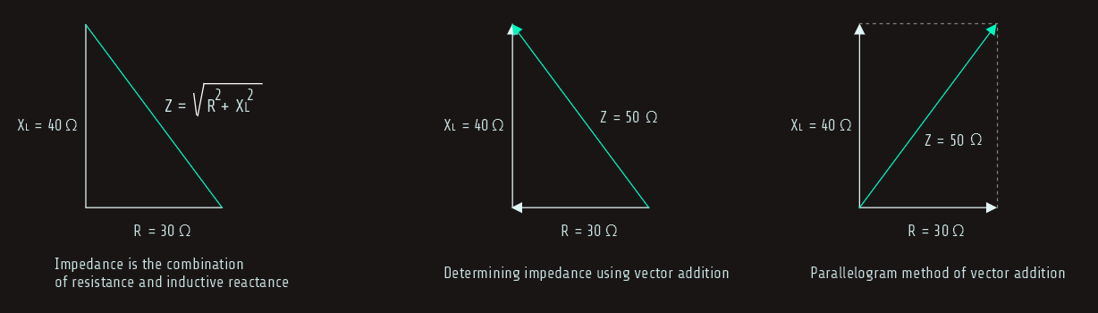
In this circuit, impedance is a combination of resistance and inductive reactance; the total impedance (Z) is the sum of the resistance and the inductive reactance. It would first appear that the sum of these two quantities should be 70 ohms (30 Ω + 40 Ω = 70 Ω). In practice, however, it is not the case; the resistive part of the circuit and the reactive part of the circuit are out of phase with each other by 90°. To find the sum of these two quantities, vector addition must be used.
Since these two quantities are 90° out of phase with each other, the resistance and inductive reactance form the two legs of a right triangle and the impedance is the hypotenuse. 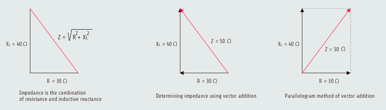
Total current
Since the impedance is the total current-limiting component of the circuit, it can be used to replace R in an Ohm’s law formula. The total current (I) flow through the circuit can be computed by dividing the total applied voltage by the total current-limiting factor, IT = ET/Z = 4.8 [A].
In a series circuit, the current is the same at any point in the circuit. Therefore, 4.8 amperes of current flow through both the resistor and the inductor.
Voltage drop across the resistor
After the amount of current flow through resistor (and inductor, also) is known, we can calculate the voltage drop across the resistor:
ER = IRxR
ER = 4.8[A]x30[Ω]
ER = 144[V]
So, we have found voltage drop across the resistor using quantities only referring to resistive part of the circuit. Although Z is combination of R and XL, we couldn't use it in voltage drop formula, or XL in this formula, and we know that R = √(Z2-XL2).
True power
True power or watts can be calculated using any of the watts formulas with pure resistive parts of the circuit. We already know that true power, or watts, can be produced only during periods of time that the voltage and current are both positive or both negative.
In an R-L series circuit, the current is the same through both the resistor and the inductor. The voltage dropped across the resistor, however, is in phase with the current and the voltage dropped across the inductor is 90° out of phase with the current. Since watts can be produced only when the current and voltage are both positive or both negative, only resistive parts of the circuit can produce watts.
P = ERxIR = 691.2[W]
We could also use another formulas: P = IR2xR, or P = ER2/R.
Inductance
We can found the amount of inductance using formula:
L = xL/(2πf)
L = 40[Ω]/377 = 0.106[H]
Voltage drop across the inductor
Only inductive quantities we will use to find the voltage drop across the inductor:
EL = ILxXL
EL = 4.8[A]x40[Ω]
EL = 192[V]
Total voltage
Although the total applied voltage in this circuit is known (240 volts), the total voltage is also equal to the sum of the voltage drops, just as it is in any other series circuit.
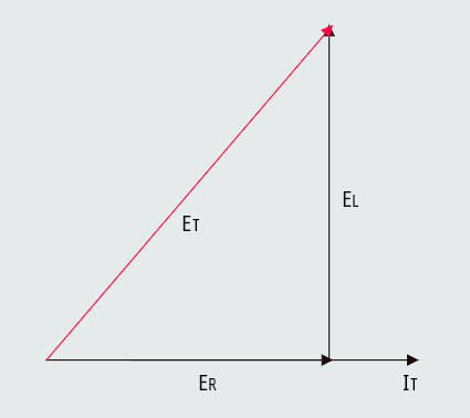
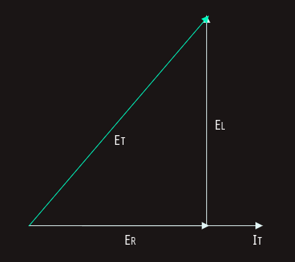
Since the voltage dropped across the resistor is in phase with the current and the voltage dropped across the inductor is 90° out of phase with the current, vector addition must be used. The total voltage will be the hypotenuse of a right triangle, and the resistive and inductive voltage drops will form the legs of the triangle. This relationship of voltage drops can also be represented using the parallelogram method of vector addition.
ET = √(ER2+EL2)
ER = √(ET2-EL2)
EL = √(ET2-ER2)
Reactive power
VARs (volt-amperes-reactive) represents the product of the volts and amperes that are 90° out of phase with each other, such as the voltage dropped across the inductor and the current flowing through the inductor.
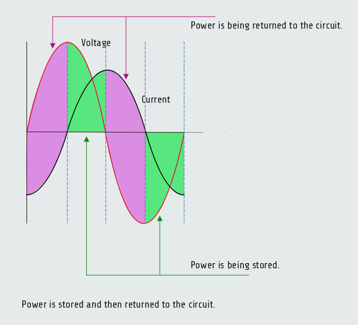
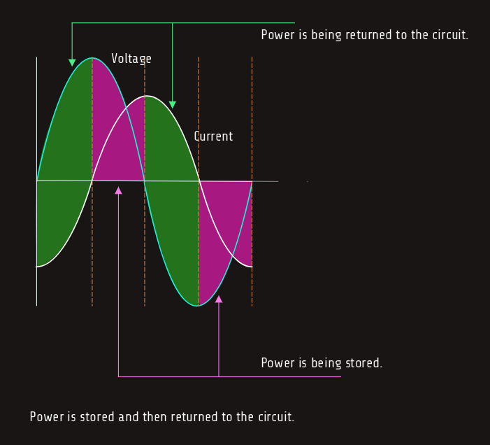
We know already that true power can be produced only during periods of time that the voltage and current are both positive or both negative. During these periods, the power is being stored in the form of a magnetic field. During the periods that voltage and current have opposite signs, the power is returned to the circuit. For this reason, VARs is often referred to as quadrature power, or wattless power.
VARs = IL2 x XL
VARs = (4.8A)2 x 40Ω
VARs = 921.6
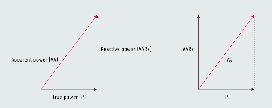
Apparent power
Volt-amperes (VA) is the apparent power of the circuit where total values of voltage and current are used. It is called apparent power (VA) because it is the value that would be found if a voltmeter and ammeter were used to measure the circuit voltage and current and then these measured values were multiplied together:
VA = ETxIT
VA = 240[V] x 4.8[A] = 1152
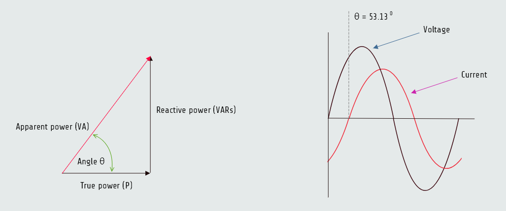
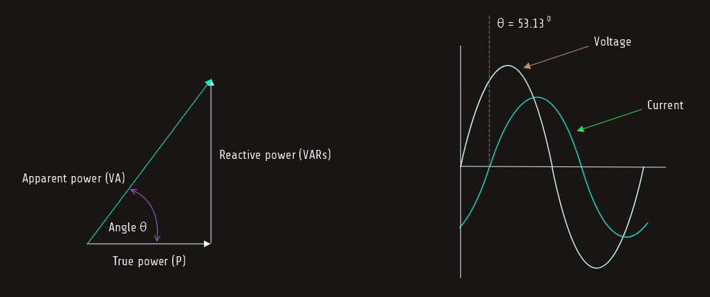
Since true power, or watts, is a pure resistive component and VARs is a pure reactive component, they form the legs of a right triangle. The apparent power is the hypotenuse of this triangle, which can be found using vector addition or parallelogram method.
VA = √(P2+VARs2) P = √(VA2-VARs2) VARs = √(VA2-P2)

Power factor
Power factor (PF) is a ratio of the true power to the apparent power; it can be computed by dividing any resistive value by its like total value.
For example, PF = ER/ET, or PF = R/Z, or PF = P/VA etc. It is usually expressed as a percentage (decimal value x 100%).
PF = P/VA = 691.2[W] x 1152 [VA] = 0,6x100 = 60 %
In a series circuit, though, the power factor cannot be computed using current because current is the same in all parts of the circuit.
Power factor can become very important in an industrial application . Electric power is sold on the basis of true power, or watt-hours, consumed. The power company, however, must supply the apparent power. Assume that an industrial plant has a power factor of 60% and is consuming 5 megawatts of power. At a power factor of 60%, the power company must actually supply 8.333 megavolt-amperes (5 MW/0.6 = 8.333 MVA). If the power factor were to be corrected to 95%, the power company would have to supply only 5.263 megavolt-amperes to furnish the same amount of power to the plant.
Angle Theta
The angular displacement by which the voltage and current are out of phase with each other is called angle theta (∠θ). The phase angle of voltage and current is formed between the resistive leg of the right triangle and the hypotenuse; the angle theta is the relationship of true power to apparent power, actually it is cosine of watts to divided by volt-amperes, which is power factor. In our case: cos ∠θ = PF, cos ∠θ = 0,6 ⇒ θ = 53,130.
Since this circuit contains both resistance and inductance, the current is lagging the voltage by 53,130.
Also, because cos ∠θ = PF = P/VA, we can use another relations:
sin ∠θ = VARs/VA
tan ∠θ = VARs/P