


It's been mentioned that the amount of charge on an individual electron is incredibly small; well, to put this in perspective, a coulomb currently equates to the amount of charge possessed by 6.241 509 129×1018 electrons! For most normal purposes, we generally round this off to 6.24×10¹⁸ electrons. So, for a current of one ampere, that is the number of electrons which are being transported past a given point in that conductor every second! The law known as Coulomb's law of electrostatic charges states that the force of electrostatic attraction or repulsion is directly proportional to the product of the two charges and inversly proportional to the square of the distance between them.
The relationship between electric charge and electric current is written as follows:
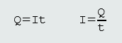
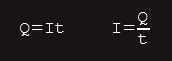
Q - quantity of charge in coulombs (C)
I - electric current in amperes (A)
t - time in seconds (s)
An electric current is defined as the quantity of electric charge, transported per unit time.
It must be clearly understood that the ampere cannot be defined as a ‘coulomb per second’, because we cannot define an SI base unit (the ampere) in terms of a derived unit (the coulomb).
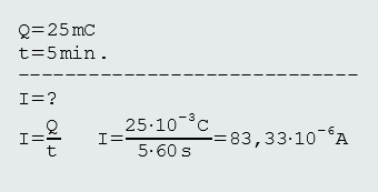
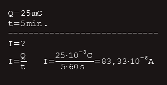
Example 1.
What is the value of current if a charge of 25 mC drifts past a point in a circuit every 5 min?
Solution:
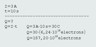
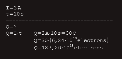
Example 2.
How many electrons will be transported past a given point in a circuit, when a current of 3 A drifts for 10 s?
Solution:
Drift velocity of charge carriers
We learnt earlier that the average velocity at which electrons move through a metal conductor is called their ‘drift velocity’, and it is surprisingly slow. It can be shown that the drift velocity along a conductor is given by the following equation:

v - drift velocity (m/s)
I - current (A)
n - number of electrons per cubic metre
A - cross-sectional area (m2)
e - charge per electron (C)
The number of electrons per cubic metre depends on the type of conductor and its purity. For copper, this value is generally taken as 85×1027 and, for aluminium, 76.2×1027. The amount of charge on a single electron is generally taken as 1.6×10⁻¹⁹ C (coulombs).
We can see that for any given conductor, the drift velocity is directly proportional to the current, and inversely proportional to the conductor’s cross-sectional area. So, for any given current, the lower the cross-sectional area of a conductor, the higher the drift velocity.
This is also true for the velocity of water as it flows from a larger-diameter tube through a smaller-diameter tube (‘venturi effect’).
Since the kinetic energy of any object is proportional to the square of its velocity, it follows that the energy released when free electrons collide with the fixed atoms in a conductor will be greater when the drift velocity is greater. So, for a given current, the energy expended by a thinner wire will be greater than for a thicker wire. This expended energy manifests itself as heat and accounts for why the temperature of a thinner wire tends to be higher than for a thicker wire carrying the same amount of current.
An electrical fuse uses this principle. A fuse wire, or ‘element’, is:
(a) thinner than the wire which it is designed to protect
(b) made from a conductor having a lower melting point.
So, when a sustained overcurrent occurs (due to a continuous overload or an electrical fault), the fuse element’s temperature rises and reaches its melting point faster than the conductor which it protects.
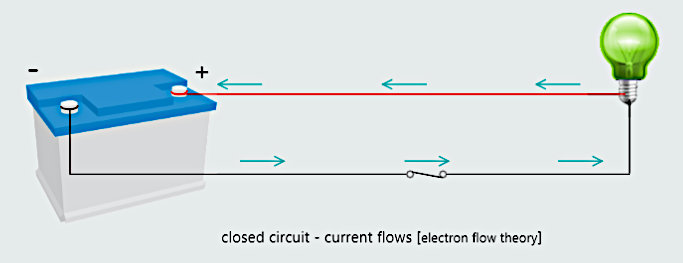
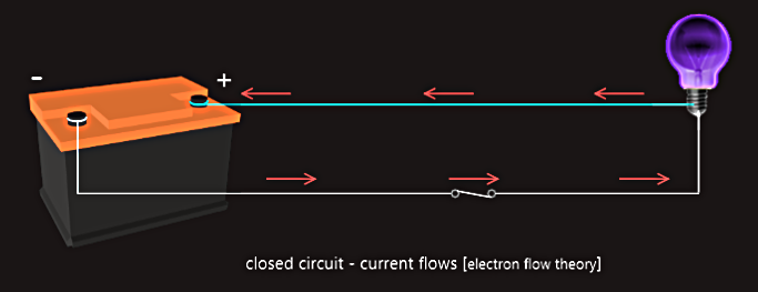
Basic electric circuits
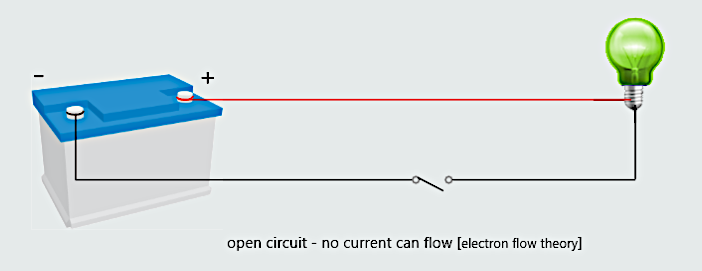
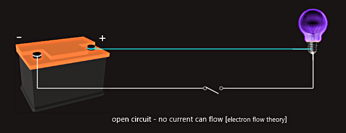
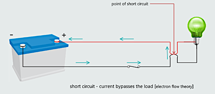
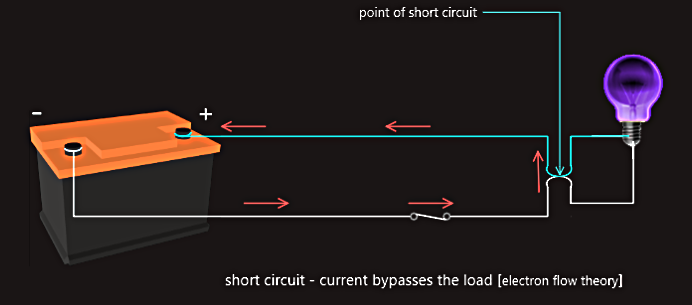
For current to flow through a circuit, there must exist a complete path. A complete path is often referred to as closed circuit, as power source, conductors and load form a closed loop. The load offers resistance to a circuit and limits the amount of the current that can flow. If the switch is opened, there is no longer closed loop and no current can flow; this type of circuit we call open circuit. Another type of circuit is short circuit that has very little or no resistance. In this case a separate current path has been established that bypasses the load, so an excessive amount of current can flow through a circuit. Short circuits generally cause a fuse to blow or a circuit breaker to open. If the circuit has not been protected by a fuse or circuit breaker, a short circuit can damage equipment, melt wires and start fires.
Another type of circuit, one that is often confused with short circuit is grounded circuit. Grounded circuits can also cause an excessive amount of current flow. They occur when a path other than the one intended is established to ground. Many circuits contain an extra conductor called the grounding conductor. The grounding conductor is generally connected to the case of the appliance to provide a low-resistance path to ground, and current will flow through it only when circuit fault happens. In normal operation, current flows through hot and neutral conductors only (although the neutral conductor is also grounded at the power source). The grounding conductor is used to help prevent a shock hazard in the event that ungrounded or hot conductor comes in contact with the case or frame of the appliance. Without a grounding conductor connected to the frame of the appliance, the frame would become "hot" and anyone touching the case and a grounded point would complete the circuit to ground; and the resulting shock could be fatal.
Potential and potential difference
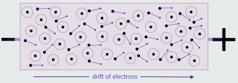
If an external negative charge is applied to one end of a metal conductor, and an external positive charge to the other end of that conductor, a drift of free electrons (an electric current) will take place through that conductor.
We describe the external negative charge as having a negative ‘potential’, and the external positive charge as having a positive ‘potential’. The difference between these potentials, therefore, is called a ‘potential difference’, and it is this which provides the ‘driving force’ for a current.

So, for charge carriers to flow between two points:
1. there must exist conducting path between those two points.
2. there must be a potential difference between the two points.
But for understanding the answer to the question of what exactly do we mean by ‘potential’ and ‘potential difference’, and where do they come from, we need a basic understanding of electric fields.
Electric fields
The area surrounding an electric charge, in which the effects of that charge may be observed, is termed an ‘electric field’.
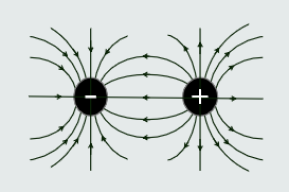
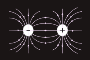
An electric field is graphically represented using lines of force, called ‘electric flux’. These electric flux lines are imaginary – the lines themselves don’t actually exist, but are used simply to provide us with a ‘model’ of an electric field in exactly the same way as magnetic lines of force are used to represent a magnetic field, which will be discussed later.

If point charges of opposite polarity are located near to each other, then these electric flux lines will link the two charges as well as extending to infinity.
But this is not a very practical definition for potential – ‘infinity’ is hardly ‘accessible’! So, instead, we choose an accessible, but arbitrary, point of reference – such as point A in figure, and then find the work done in transporting the charge from that point to point B. Hence, we determine the potential at point B with respect to point A. This allows us to determine the potential difference between points A and B.
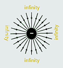
We can now imagine moving a free electron from infinity, along one of these lines of electric flux, towards a fixed negative charge, as illustrated in figure below. As ‘like poles repel’, work must be done to overcome the force of repulsion due to the fixed negative charge, in order to move that electron the distance from infinity to point B. The work done in moving the electron results in an increase in that electron’s potential energy or, simply, its ‘potential’.
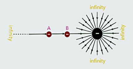
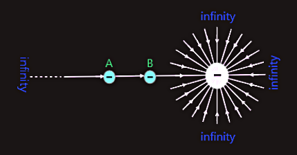
The absolute potential at any point along a line of electric flux is defined in terms of the work done in moving a negative charge (in figure - a single electron but, in practice, a negative charge equal to one coulomb) from infinity to that particular point (point B).
The potential difference between two points in an electric field is defined in terms of the work done in transporting electric charge between those two points.
The term ‘voltage’ is synonymous with ‘potential difference’ (but not potential)! The symbol for potential difference or voltage is E, U or V.