It is believed that equation  is an expression of ‘Ohm’s Law’.
It can be often found in literature that:
Ohm’s Law states that ‘the current in a conductor is directly proportional to the voltage across that conductor, and inversely proportional to its resistance’.
However, that is not what Ohm’s Law says!
But, this is so well ingrained into the teaching of electrical science that equation will likely to continue to be known as the ‘formula for Ohm’s Law’!
This equation will always tell us what the current happens to be for a particular combination of potential difference and resistance. And it applies under all circumstances, whether a circuit obeys Ohm’s Law or not!
So now, we can ask a question what then, is Ohm’s Law?
Ohm's Law
In 1827, a physics teacher from Germany, by the name of Georg Simon Ohm (1789–1854), published the results of a series of experiments in which he had established a relationship between the current in a wire and the potential difference applied across the ends of that wire.
Ohm’s Law states that ‘the current in a wire at constant temperature is directly proportional to the potential difference across its ends’, I ~ E.
Or putting it in another way, we can say that the ratio of voltage to current is a constant:  .
.
During the course of his experiments, Ohm found that changing the type of wire resulted in a different ratio of voltage to current, resulting in different value to the constant k. From this, he concluded that k must represent some form of physical property for a particular wire.
Furthermore, since, for a given potential difference, the current must decrease if the value of k increases, then he concluded that k must represent some form of opposition to the drift of current. This opposition to current is named ‘resistance’, and the unit of measurement ohm (Ω).
If the resistance (i.e. the ratio of voltage to current) of a conductor always remained constant for variations in applied voltage, then Ohm’s Law would always be true.
But, the resistance of a conductor (and other circuit components) does not always remain constant for variations in applied voltage.
And this means that Ohm’s Law is not always true!
Ohm's experiments
Ohm’s Law is not a ‘universal’ law. That is to say, unlike most other scientific laws, Ohm’s Law does not apply to all circuits or electronic components under all circumstances!
There are ‘sensible’ materials and devices which actually obey Ohm’s Law and those are termed ‘linear’ or ‘ohmic’; those ‘rogue’ materials which do not obey Ohm’s Law are called ‘non-linear’ or ‘non-ohmic’. So, only ‘linear’ or ‘ohmic’ materials obey Ohm’s Law, and there are far fewer of these than ‘non-ohmic’ or ‘non-linear’ materials.
Most pure metals are ‘linear’ or ‘ohmic’ to some extent, and obey Ohm’s Law, providing their temperatures remain approximately constant. But conducting liquids (electrolytes) and ionised gases are ‘non-linear’ or ‘non-ohmic’ conductors, and do not obey Ohm’s Law. In the case of electronic devices and components, we would discover, from examining their characteristic curves, that diodes, transistors, thermionic valves (tubes) etc., are either completely or partially ‘non-linear’.
Linear conductors
To perform the modern-day equivalent of Ohm’s experiment, we can use the simple circuit shown in the next figure, comprising a variable-voltage supply, a voltmeter to measure changes in the potential difference across a resistor, and an ammeter to measure the resulting currents.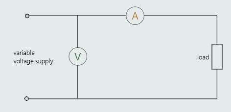
 By simply increasing the potential difference across the resistor in uniform increments, and noting the corresponding values of current, we can use our results to construct a graph.
As it’s important to prevent the temperature of the resistor from increasing during the experiment, we must ensure that the range of voltages we apply to the resistor don’t result in currents that are high enough to cause the resistor’s temperature to increase.
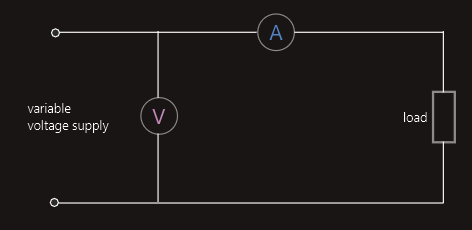
It is standard practice, when constructing any graph, to plot the quantity which we intentionally vary (called the ‘independent variable’) along the horizontal axis, and the quantity which changes as a result of changes in the first quantity (the ‘dependent variable’) along the vertical axis.
So, for this experiment, it is usual to plot the voltage along the horizontal axis, and the resulting current along the vertical axis.
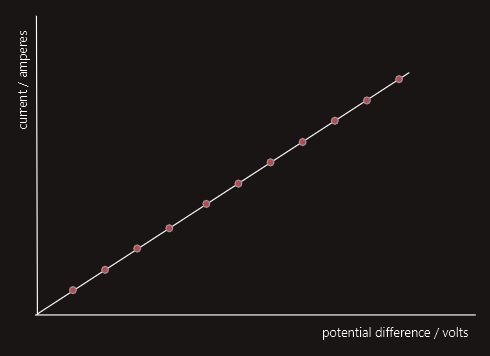 The straight-line (i.e. ‘linear’) graph indicates constant proportionality between the dependent and independent variables.
We can describe Ohm’s Law as being a law of constant proportionality.
A proof of Ohm’s Law would be:
If the ratio of potential difference to current for a particular conductor or device remains proportional for variations in that potential difference, then that conductor or device obeys Ohm’s Law.
Providing their temperatures are kept constant, most metal conductors are ‘linear’. Some alloys, such as constantan are deliberately manufactured so that their resistance remains approximately constant over a wide range of temperatures.
Fixed-value resistors, which are circuit components used to modify the natural resistance of a circuit, must be manufactured from ‘linear’ conductors because it is important that their specified values of resistance remain constant for voltage/current variations within their power ratings.
Non-linear conductors
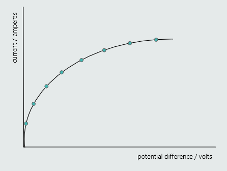
One of the conditions necessary for Ohm’s Law to apply is that the temperature of the conductor must remain constant during the experiment. So what would happen if that temperature were allowed to vary during the above experiment? For example, what would happen if we were to repeat the same experiment but using, say, a tungsten-filament lamp and incrementally increased the voltage right up to the lamp’s rated voltage? Well, instead of producing a straight-line graph, our experiment would produce a curved (i.e. a ‘non-linear’) line – similar to that shown in figure.
The reason for this is that, as the current through the lamp increases during the course of the experiment, the temperature and, therefore, the resistance of its tungsten filament continually increases, and increases significantly!
The curved-line graph confirms that changes in potential difference do not produce proportional changes in the resulting currents. That is, the ratio of voltage to current varies continuously throughout the experiment – confirming that the increasing temperature of a tungsten filament prevents it from obeying Ohm’s Law!
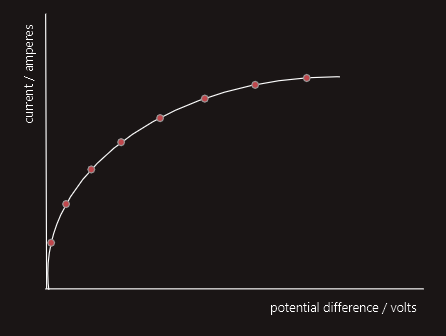
Although this non-linear curve mean that Ohm’s Law doesn’t apply, the equation  remains valid, which can be applied at any point along that curve, and will tell us what the resistance happens to be only at those particular points.
What we cannot do, for non-linear materials, is to use that equation to predict what the resistance will be at some other point along the curve. This is because the resistance is not dependent on this equation, but upon the temperature at those other points.
The voltage/current characteristic curves of various electronic components, such as diodes, transistors, thermionic valves (tubes) etc. are either entirely non-linear, or are a combination of linear/non-linear! Interestingly, for a tunnel-diode, for example, the part of the curve is not only non-linear, but it has a negative slope, which means it displays a negative-resistance characteristic – that is, as the voltage increases, the current falls (nonlinearly, in this case)! And this, of course, completely contradicts Ohm’s Law!
We must mention the fact that for some circuit examples we simply don’t know if they obey Ohm’s Law – there could be no information supplied which tells us whether the ratio of potential difference to current remains constant at other voltages (if the potential difference across a circuit is given). If ratio does remain constant, then they do; if the ratio changes, then they don’t! But whether they obey Ohm’s Law or not is irrelevant to the solutions, as the equations we have used apply under any circumstances.
Example:
The voltage applied to a particular circuit is 12 V, and the resulting current is 6 A. The voltage is then increased to 60 V, and the resulting current is found to be 30 A. Does the circuit obey Ohm’s Law?
Solution:
At the beginning of the experiment R = E/I = 12/6 = 2Ω
At the end of the experiment R = E/I = 60/30 = 2Ω
As the resistance has remained constant, the ratio of voltage to current has changed, so Ohm’s Law does apply, within that range of voltages.
Series, parallel and series-parallel circuits
In order for charge carriers to flow, there must be a continuous external conducting path, called a circuit, between the terminals of a source of electromotive force (e.g. a battery, generator, etc.) and a load (e.g. a lamp, electric heater, etc.). This continuous ‘conducting path’ is termed a closed circuit. If there is a break anywhere in this conducting path, then there can be no current and it’s termed an open circuit.
Circuits are categorized according to the way in which they are connected. There are four such categories:
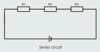
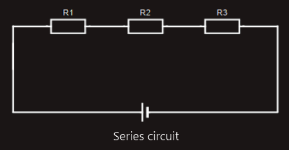
1. series circuit
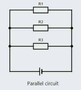
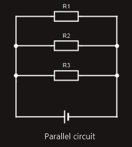
2. parallel circuit
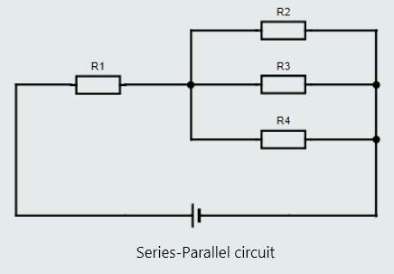
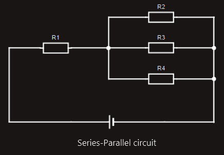
3. series-parallel circuit
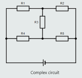
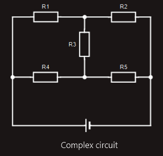
4. complex circuit