


There are two types of pushbuttons, available for commercial use:
1. momentary pushbuttons
2. locked-position pushbuttons
Momentary pushbuttons change state from open to closed or vice versa and they remain at the changed position only as long as they're pressed; when they are released, they return to their normal state.
Locked-position pushbuttons are similar to switches; they change state permanently each time they are pressed.
Switches can be categorized in two main categories:
1. manual switches
2. automatic switches
Manual switches require an operator to change their state.
Automatic switches are controlled by a mechanical or electrical device, such as thermostat, controlled by temperature level, or limit switches which sense some limit, such as fluid level, pressure, mechanical movement etc. to change their state.
Sensors
Electronic sensors are used in PLC control systems to detect changes in the environment and in industrial settings. They can emulate five human senses and convert the changes to electronic signals. Electronic sensor output basically provides logic high or low output. The signal from electronic sensor can also provide a range of current or voltage levels.
Proximity sensors, for example, use a light-emitting diode (LED) and a phototransistor to open or close a circuit when the presence of an object is detected. LED emits light when a current flows through it. It serves as a transmitter that generates infrared light beam through the proximity switch. A phototransistor allows current to flow from its collector to the emitter when a beam of light strikes its base. It serves as the receiver that detects the presence of the light beam emitted from the LED. The sensor is triggered when the light beam is interrupted by the objects placed in the light beam's path.
RADAR sensors (Radio Detection And Ranging) are used to detect metallic objects. RADAR sensors transmit several cycles of high-frequency waves into the environment and pick up the reflection through a receiver. Object's shape details are more accurate when transmitting a smaller width beam. In this case, large antenna must be used, because the width of the beam is inversely proportional to the size of the transmitter antenna.
There are also inductive sensors, capacitive sensors, optical sensors, temperature sensors available, as many other sensors, also.
Indicators
Indicators are used to help an operator to visually inspect the operation of an output device. Different colored lights, such as red, green and yellow visually show each stage or operating condition of an output device.
Relays
Relays are electrically operated control switches and are one of the most frequently used devices in modern technological systems. They can be found in cars, washing machines, microwave ovens, medical equipment, as well as tanks, airplanes and ships. In some complex automatic control systems in the industry, the number of relays is estimated to be hundreds or even thousands. In the power generation industry, no power equipment is allowed to operate without special protective relays. Certain electrical equipment, such as power transformers, may be protected by several different types of relays, each of which controls different functions.
Relays are classified as power relays and control relays. Power relays are often called contactors, control relays are usually known simply as relays. The difference between relays and switches is that relays use a coil to generate magnetic effect. The magnetized or demagnetized coil causes the relay's contacts to either close or open. Multiple pole relays can be used to control several contacts and circuits at once.
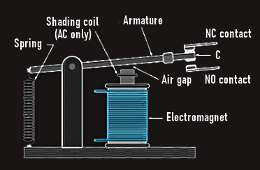
In general, a relay consists of a magnetic core, coil, contacts, spring, armature, mounting and terminals.
The spring pulls the armature C upward, and it forces the C to hit the NC terminal when no energy is applied to the coil. When coil is energized, an electromagnet is formed and absorbs the armature C downward. When armature C goes down and hits the terminal NO, a connection between C and NO is formed. When coil is not energized, the spring brings the armature C upward and it hits the NC again. 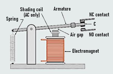
 Important types of relays are: SPST (single pole single throw), SPDT (single pole double throw), DPST (double pole single throw), and DPDT (double pole double throw).
Each relay works with a certain voltage. The required operating voltage for the coil and current allowed to pass through relay contacts is printed on the relay case.
A contactor uses a relatively small amount of electrical power to control the switching of a large amount of power, which is important to safety and implies that high-power circuits can be switched remotely without danger to the operator.
Control relays are typically used in the control of low-power circuits or other relays.
A solenoid is similar to relay except that inserted within the solenoid coil is a soft-iron core and movable plunger. It is a control device that uses electromagnetism to convert electrical energy into mechanical motion. The core is pulled and pushed by the magnetic field and solenoid spring. When voltage is applied, the current through the coil produces magnetic field. This magnetic field draws the plunger within the coil, resulting in mechanical motion. When the coil is de-energized, the spring returns the plunger to its normal position. 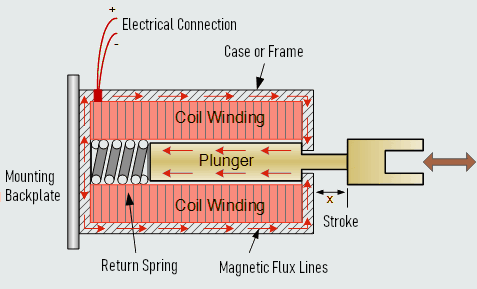
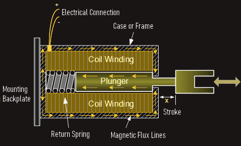
Opening and closing a valve to control the flow of liquid or gas is commonly used application of the solenoid.
Motor Control Devices
Two major types of motor control devices are motor starters and motor drives.
Motor starter simply turns a motor on and off. It incorporates a motor-protective device, to protect the motor from low voltage, high temperature and high load current (overload conditions).
Motor drive controls the operating characteristics of a motor, such as velocity, acceleration and deceleration.
Motor starters have two main sections: contactors and overload protection. The overload protective devices in the motor starter are called overload relays.
Motor drives draw electrical energy from the mains and supply the electrical energy to the motor at whatever voltage, current and frequency necessary to achieve the desired torque and speed output. Starting and stopping the motor is done by a discrete signal (on and off), while regulating the speed of the motor is done by a variable (analog) signal. Motor can be reversed in its direction of rotation. The motor is decelerated down to zero speed and then the direction of field current flow is reversed and increased so that the motor accelerates to its operating speed.
Fundamentals of Logic (Logic Gate Functions)
The PLC, as a digital equipment, operates on the binary principle, the states 1 and 0, which represents two conditions: ON or OFF, open or closed, true or false, high or low, or any other possible conditions. There is no in-between state so when information is processed the outcome is either 'yes' or 'no'.
A logic gate is a circuit with several inputs but only one output that is activated by particular combinations of input conditions. Logic is the ability to make decisions when one or more different factors must be taken into account before an action is taken, which is the basis for the operation of the PLC, where it is required for a device to operate when certain conditions have been met.
There are seven logic gates: NOT, AND, OR, NAND, NOR, XOR (exclusive OR), and XNOR (exclusive NOR). These logic gates do not require clock pulses to operate; the outputs of these gates are generated instantaneously; the outputs depend only on their present inputs. They are also called combinational logic gates.
Sequential logic devices have outputs that depend on their current inputs, as well as past inputs, so they require clock pulses.
Flip-flop devices such as RS (reset-set), JK, D (delay) and T (toggle) are sequential logic devices.
AND, OR, and NOT Functions
The operations performed by digital equipment are based on three fundamental logic functions: AND, OR, and NOT.
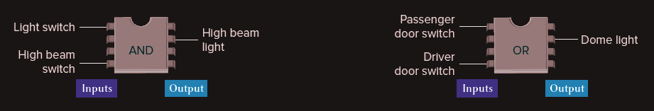
For example, the high beam automobile lighting circuit is an example of a logical AND decision. Here, the high beam light can be turned on only when the light switch AND the high beam switch are closed.
In addition, the dome light automobile circuit is an example of a logical OR decision. For this application, the dome light will be turned on whenever the passenger door switch OR the driver door switch is activated. 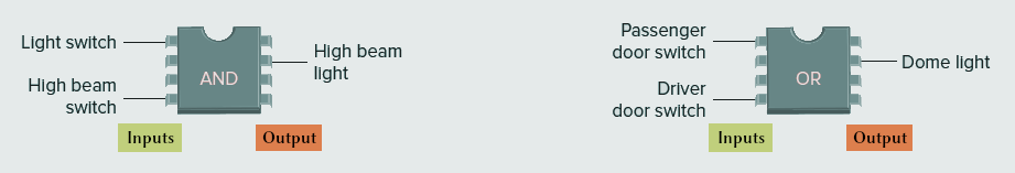
The AND Function
An AND gate is a device with two or more inputs and one output. The AND gate output is 1 only if all inputs are 1, otherwise it is 0. 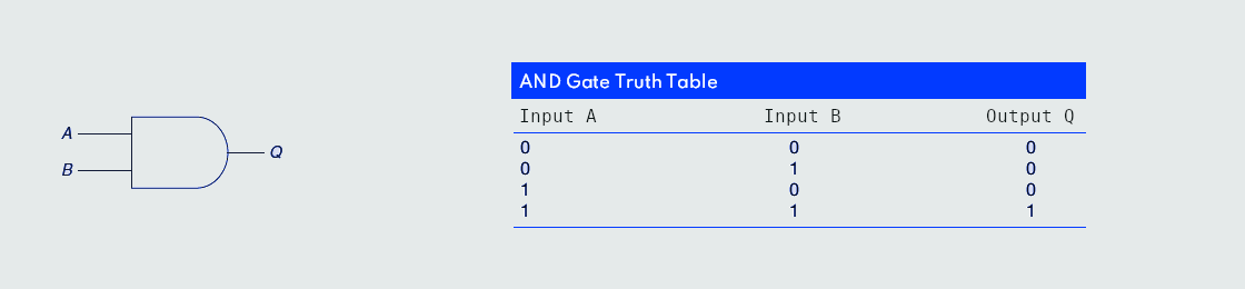
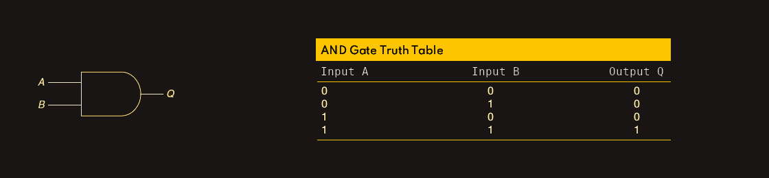 The AND logic gate operates similarly to control devices connected in series, like two switches, light and source. The light will be on only when both switch A and switch B are closed.