Energy consumption
As we have learnt, in SI the unit of measurement for work or energy is joule. The joule represents a very small quantity of energy, so more practical units are megajoule or gigajoule. However, electricity supply companies have never adopted these units but use, instead, the kilowatt hour (kW·h), which is equivalent to 3.6 MJ.
Kilowatt hour is the work done by a load, at a rate of one kilowatt, over a period of one hour.
The energy used by residential consumers is measured using an instrument called an energy meter. The energy consumed during a billing period is the difference between the current meter reading and the previous meter reading.
So, if a 3 kW heater was in use for 12 hours the amount of energy used would be 129.6 MJ. In order to record this the meter would require at least ten dials to indicate this very large number. In addition to which, many of them would have to rotate at an impossible rate. Hence the commercial unit of energy is the kilowatt-hour (kWh). Kilowatthours are the ‘units’ that appear on electricity bills. For the heater mentioned above, the number of ‘units’ consumed would be written as 36 kWh. To record this particular figure, fewer dials are required, and their speed of rotation is perfectly acceptable.
‘Smart’ meter is a digital energy meter, which records electrical energy consumption in intervals of one-hour or less, and wirelessly communicates that data directly to the electricity supply company, without the need for a meter reader to visit the consumer’s location. Smart meters also inform the consumer how much energy is being consumed, together with its cost, in near real-time, via a separate in-home display monitor.
Traditional mechanical or electronic energy meters only measure the quantity of energy consumed, and provide no information on when that energy is being used.
D.C. circuits
We have seen earlier resistors connected in series, parallel, series-parallel and complex circuits, and we have learned the procedure of getting total resistance of such circuits. Also, we showed some practical uses of those connections, for example of resistors connected in series there is a usage in a form of potential divider. Other then potential divider, there is also current divider. When resistors are connected in parallel the total circuit current divides between the alternative paths available. Branch currents are determined by calculating the common p.d. across a parallel branch and dividing this by the respective resistance values.
However, these currents can be found directly, without the need to calculate the branch p.d., by using the current divider theory. The theory is based on using ratio of currents flowing through each branch in respect with total current. After calculating branch currents, we can solve the circuit respecting some already known procedure.
We have also explained three laws:
- • Ohm's Law
- • Kirchhoff’s Voltage Law
- • Kirchhoff’s Current Law
Wheatstone bridge
One of the most common devices used to measure values of resistance, inductance, and capacitance accurately is a bridge circuit. A bridge is constructed by connecting four components to form a parallel-series circuit. All four components are of the same type, such as four resistors, four inductors, or four capacitors.
The bridge used to measure resistance is called a Wheatstone bridge.
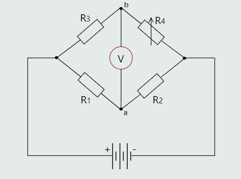
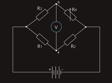
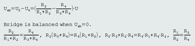
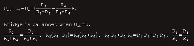
The variable resistor R4 is adjusted until the voltmeter reads zero volts. At this point we say that the bridge is balanced. If we know the value of three of the resistors in a balanced Wheatstone bridge circuit we can calculate the value of the fourth resistor. If a Wheatstone bridge is balanced the voltmeter will have a zero reading.
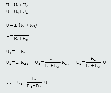
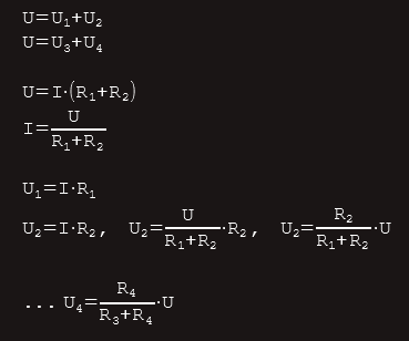
When a Wheatstone bridge is balanced  .
.
Wheatstone bridge has two voltage dividers connected in parallel.
The resistor pair R1 and R2 is one voltage divider, and resistors R3 and R4 form another voltage divider in parallel with the first one.
Adding another variable resistor results in a more sensitive circuit - in which R1 and R4 are both variable resistors (transducers/sensing elements).
Wheatstone bridge is a simple circuit used to measure transducer responses by measuring changes in voltage.
Basic circuit analysis is used to determine the resistance when the bridge is balanced.
Any changes in transducer resistance cause the bridge to be unbalanced providing a voltage roughly proportional to the change in resistance and corresponding to the change in pressure.
A voltmeter measures the output of the Wheatstone bridge which can be equated to a corresponding pressure.
In a micro pressure sensor where the Wheatstone bridge is the sensing circuit, its output can be amplified and processed to send information or to initiate a mechanical response.
Electric fields and capacitors
Coulomb’s Law
A force exists between charged bodies. Between opposite charges a force of attraction exists and a force of repulsion between like polarity charges. Coulomb’s law states that the force is directly proportional to the product of the charges and is inversely proportional to the square of the distance between their centres,  .
.
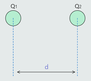
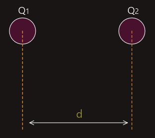
In order to obtain a value for the force, a constant of proportionality, in this case it is the permittivity of free space (Ɛ0), must be introduced 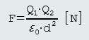 .
.
This relationship follows an inverse square law, so if the distance of separation is doubled then the force will be reduced by a factor of four times. If the distance is increased by a factor of four times, the force will be reduced by a factor of sixteen times, etc. This will continue until a point is reached where the force, that can never be reduced to zero, is negligible relative to other forces acting within the system.
Electric field
An electric field is simply a means, just like magnetic and gravitational fields, of transmitting the forces involved, from one body to another. However, the field cannot be detected by the human senses, since we cannot see, touch, hear or smell it. It is the method by which forces are transmitted between charged bodies. We can represent the appropriate field by means of arrowed lines. These lines are usually referred to as the lines of force.
When there are two oppositely charged spheres with a small positively charged particle placed on the surface of Q1, then the small charged particle will experience a force of repulsion from Q1 and one of attraction from Q2. The particle will trace out a curved path until it reaches the surface of Q2. If this was carried out for a number of starting points at the surface of Q1, the paths taken by the particle would be as shown on the next figure:
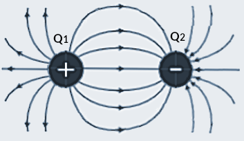
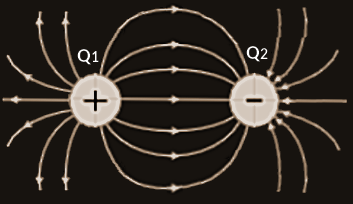
The lines shown represent the possible paths taken by the positively charged particle in response to the force acting on it. Thus they are called the lines of electric force. They may also be referred to as the lines of electric flux Ψ.
We can see on the figure that the spacing between the lines of flux varies depending upon which part of the field we consider. This means that the field shown is non-uniform.
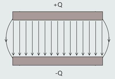
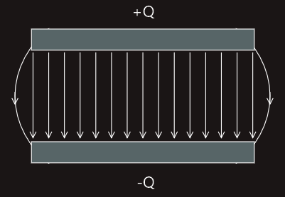
A uniform electric field may be obtained between two parallel charged plates.
Electric field will exist in all of the space surrounding the two plates, but the uniform section exists only in the space between them. Some non-uniformity is shown by the curved lines at the edges (fringing effect).
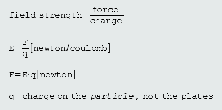
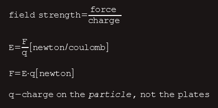
If a positively charged particle was placed between the plates it would experience a force that would cause it to move from the positive to the negative plate. The value of force acting on the particle depends upon what is known as the electric field strength.
Electric field strength
Electric field strength is defined as the force per unit charge exerted on a test charge placed inside the electric field.