


Programmable Logic Controller (PLC) Overview
A Programmable Logic Controller, a PLC or programmable controller, is a computer-type device used to control equipment in an industrial facility. The kinds of equipment that PLCs can control are as varied as industrial facilities themselves. In a traditional industrial control system, all control devices are wired directly to each other according to how the system is supposed to operate. In a PLC system, however, the PLC replaces the wiring between the devices; it has eliminated much of the hardwiring associated with conventional relay control circuits. Thus, instead of being wired directly to each other, all equipment is wired to the PLC. Then, the control program inside the PLC provides the “wiring” connection between the devices. The control program is the computer program stored in the PLC’s memory that tells the PLC what’s supposed to be going on in the system.
Initially the PLC was used to replace relay logic, but its ever-increasing range of functions means that it is found in many and more complex applications. Because the structure of a PLC is based on the same principles as those employed in computer architecture, it is capable not only of performing relay switching tasks but also of performing other applications such as timing, counting, calculating, comparing, and the processing of analog signals. Relays have to be hardwired to perform a specific function. When the system requirements change, the relay wiring has to be changed or modified. The use of a PLC to provide the wiring connections between system devices is called softwiring.
Parts of a PLC
The PLC consists of at least four main units:
1. Central processing unit (CPU)
2. Power Supply
3. Input module(s)
4. Output module(s)
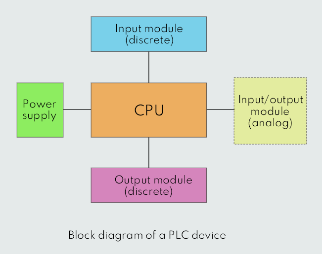
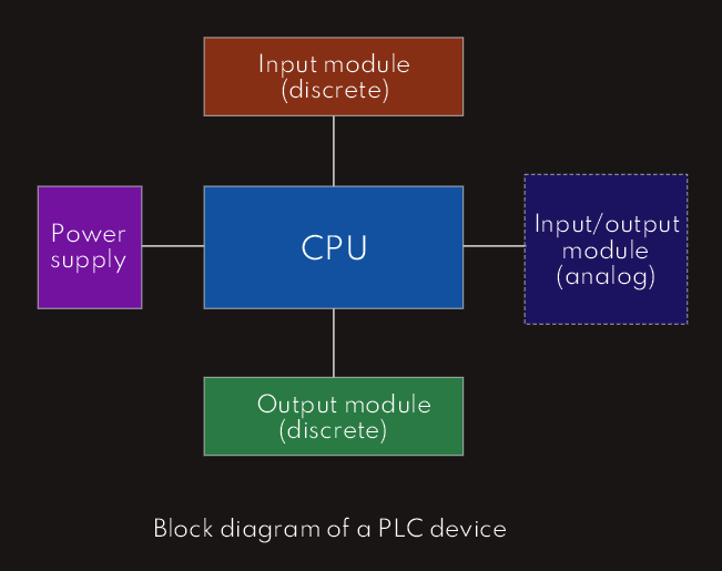
Discrete input ports are ports on a PLC input module that receive fixed signals; they are either open (OFF), or closed (ON). Discrete output ports are ports on a PLC output module that are either energized (ON) or de-energized (OFF). Larger and more advanced PLCs also have analog, or variable input and output ports. Variable input ports can receive variable voltage (0V to 10V, for example) or variable current (4mA to 20mA, for example) and convert it to binary data using converter chips. Variable output ports perform the opposite function; they convert binary data into an analog signal, such as variable voltage and current.
When the CPU, input port and output port of PLC are in one fixed enclosure, that PLC is known as fixed PLC, while we, also, have another - modular PLC in which each unit is placed in a different rack.
An open architecture design allows the system to be connected easily to devices and programs made by other manufacturers, while a system with a closed architecture is one whose design is proprietary, making it more difficult to connect to other systems.
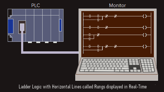
The central processing unit (CPU) usually consists of a microprocessor unit, memory and support chips. Microprocessor is responsible for implementing the logic and controlling the communications among the modules. The processor requires memory for storing user program instructions, numerical values, and I/O devices status. The CPU controls all PLC activity and is designed so that the user can enter the desired program in relay ladder logic; user creates program in ladder logic and downloads it to the PLC. Control program of PLC can be displayed on a monitor in real time.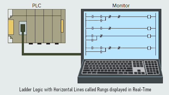
There are two types of internal memory available to a CPU:
1. RAM (Random Access Memory) - can be written to and read from, used for temporary data storage.
The PLC program resides in the RAM. There are two types of RAM - static RAM (SRAM) and dynamic RAM (DRAM).
SRAM stores data bits in its internal flip-flops, it is faster than dynamic RAM, usually cache memory uses SRAM. Data on SRAM remains the same as long as it is not overwritten by newer data and power to the memory device is on. A flip-flop is a sequential digital device that generates a different output for every input on the next clock pulse.
DRAM stores data in the form of charge on capacitors. Data on DRAM must be refreshed every few microseconds, due to the discharge of the capacitors.
Smaller and medium size PLCs use SRAM, while larger and more advanced PLCs may use DRAM.
2. ROM (Read Only Memory) - can be read from, but cannot be written to, and it holds the permanent system program.
There are four different types of ROM:
· Masked (preprogrammed) ROM
· Programmable ROM (PROM)
· Erasable Programmable ROM (EPROM) or ultra-violet erasable programmable ROM (UVEPROM)
· Electrically Erasable PROM (EEPROM) or flash ROM.
The ROM in the PLC CPU is preprogrammed by the manufacturer and it contains basic input/output system (BIOS). BIOS holds software called power-on self-test (POST) which executes on powering up a PLC, initializes the PLC system and carries out several other instructions that check the input, output and peripherial devices connected to the CPU.
Operation principle
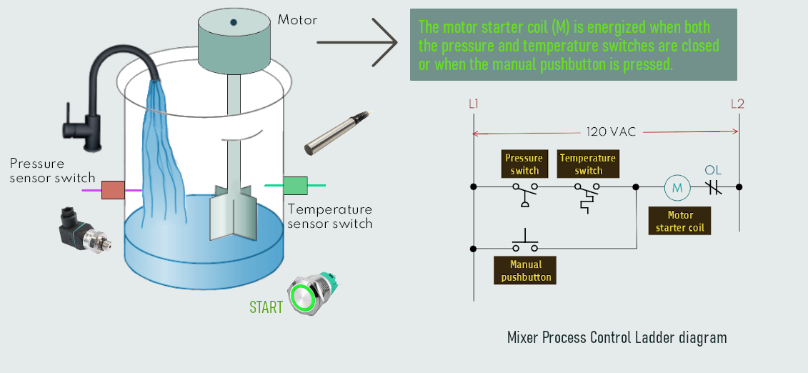
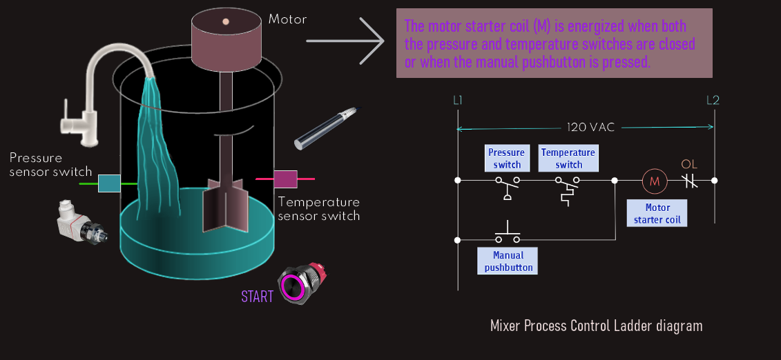
When we use a PLC for this application, the same input field devices (pressure switch, temperature switch, and pushbutton) would be hardwired to an appropriate input module according to the manufacturer’s addressing location scheme. The same output field device, i.e. motor starter coil would also be used. This device would be hardwired to an appropriate output module according to the manufacturer’s addressing location scheme. So next, the PLC ladder logic program would be constructed and entered/downloaded into the memory of the CPU.
A typical ladder logic program for this process is shown in figure below; the individual symbols represent instructions, whereas the numbers represent the instruction location addresses on input and output modules.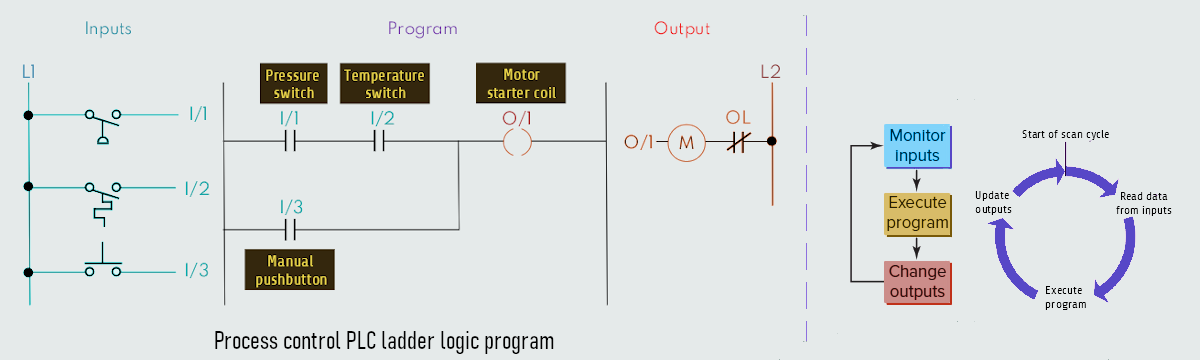
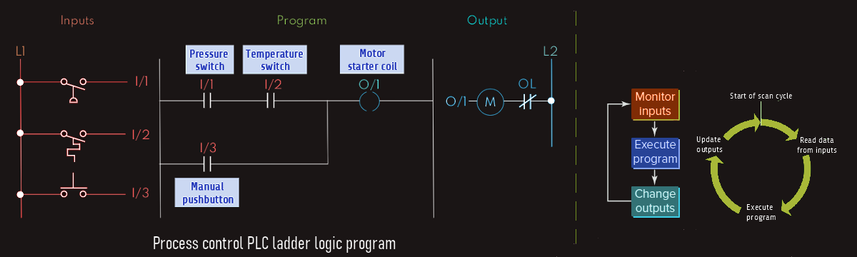
During the program scan the controller monitors the inputs, executes the control program, and changes the output accordingly.
In the ladder logic program shown above, the coil O/1 is energized when contacts I/1 and I/2 are closed or when contact I/3 is closed. Either of these conditions provides a continuous logic path from left to right across the rung that includes the coil.