


Within a computer, at a fundamental level, there are two methods of representing and manipulating data:
1. numerical - where the result of an operation is in a numerical form
2. logical - where the result has only two possibilities, expressed as ‘yes’ or ‘no’, ‘true’ or ‘false’, ‘1’ or ‘0’.
Logical functions can be applied on single bits, bytes (8 bits) and complete words (16 bits or 2 bytes); a single bit can only take the form of 1 or 0; when it is 1, it is said to be set and when it is 0, it is said to be reset. Logical functions can be carried out using electronic circuits called logic gates.
The logical operators are AND, OR, XOR, NOT, NAND, NOR and XNOR. Each has its own rule set that can be represented by a truth table, which shows a number of inputs and the output after the rules are applied.
The logical AND operator, also called MASK, has the following rule set:
All inputs must be true (VALUE 1) for the output to be true.
<We have seen earlier how truth table for AND looks like...>
The logical OR operator, also called UNION, has the following rule set:
If any of the inputs is true, then the output will be true.
<We have seen earlier how truth table for OR looks like...>
The logical XOR (or ‘exclusive OR’ or ‘EOR’) operator, also called DIFFER, has the following rule set:
One input, and only one input, must be true for the output to be true.
<We have seen earlier how truth table for XOR looks like...>
The logical NOT operator, also called NEGATE, has a single input and the output is the opposite state to the input.
<We have seen earlier how truth table for NOT looks like...>
The logical NAND operator applies the output of AND to the input of NOT, so it reverses the AND output.
<We have seen earlier how truth table for NAND looks like...>
The logical NOR operator applies the output of OR to the input of NOT, so it reverses the OR output.
<We have seen earlier how truth table for NOR looks like...>
The logical XNOR operator applies the output of XOR to the input of NOT, so it reverses the XOR output.
<We have seen earlier how truth table for XNOR looks like...>
We can also construct truth tables with more than two inputs, and common practice is to use Q to represent the output.
Boolean algebra
Boolean algebra, developed by the English mathematician George Boole, deals with variables that can only have two values like ‘yes’ or ‘no’, ‘true’ or ‘false’, ‘1’ or ‘0’, so it maps exactly onto the binary system.
- AND is same as multiplication (0x0 = 0, 0x1 = 0, 1x0 = 0, 1x1 = 1)
- OR is same as addition (0+0 = 0, 0+1 = 1, 1+0 = 1, 1+1 = 1, actually it is 2, but we are using binary and it is not 0, so we accept the compromise.)
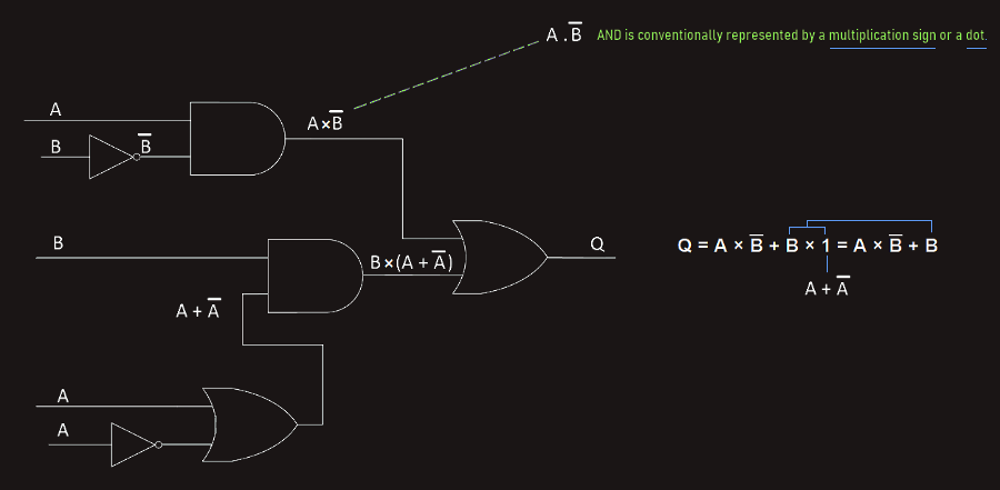
AND is represented as x, A AND B = A x B
OR is represented as +, A OR B = A + B
NOT is represented as 'overscore', NOT A = ‾A‾ or sometimes with an exclamation mark, A! (NOT gate is called 'inverter').
A XOR B = A ⊕ B
Some common Boolean laws are:
1. Commutative law, A x B = B x A, A + B = B + A
2. Distributive law, A × (B + C) = A × B + A × C, A + (B × C) = (A + B) × (A + C)
3. Associative law, A × (B × C) = (A × B) × C, A + (B + C) = (A + B) + C
One interesting rule is for a variable that is inverted twice, then the result is always equal to the variable.
De Morgan’s law
De Morgan’s law is a way of minimalizing difficult statements by simplifying some logic expressions:
1. The first rule is that two separate terms NOR-ed together are the same as the two terms inverted and AND-ed.
‾(A + B)‾ = ‾A‾ × ‾B‾
2. The second rule is that two separate terms NAND-ed together are the same as the two terms inverted and OR-ed.
‾(A x B)‾ = ‾A‾ + ‾B‾
We can demonstrate that De Morgan’s law is correct by using truth tables...
De Morgan’s law can be extended to any number of variables, for example: ‾(A + B + C)‾ = ‾A‾ × ‾B‾ x ‾C‾
Karnough map (or K-map) is another method for simplifying Boolean equations; it's a way of representing a logical expression and identifying its simplest form graphically by using some simple rules. Now, we will not go in details here, but it is useful to know that there are some other methods for simplifying Boolean equations, also.
Simplifying logical equations allows us to reduce a logic network needed to carry out a given operation to the minimum number of logic gates, thereby reducing the hardware requirement.
So, the logical operations we have been working with can be carried out using logic gates. These logic gates are analyzed in sections before - where we have seen logic gates symbols and truth tables for different operations. 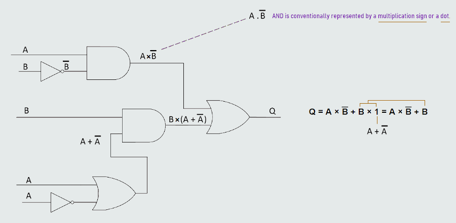
NAND and NOR gates are often referred to as universal logic gates; for example we can construct an XOR gate from NAND gates.
Various combinations of these logic gates are used to construct more complex devices that can carry out complex operations in computers, such as adders, flip-flops and registers.
Regarding to adders, we have half-adder (where there is Sum and Carry) and full-adder; the half-adder only carries out the addition of two bits and generates a carry bit of 0 or 1 as appropriate. In order to add more than two bits, for example to add a byte or a word, we need to consider that, when two digits are added together, they have a sum and perhaps a carry, but there may be a carry from a previous stage and the half-adder has no way of dealing with that. Therefore, we need a series of adders, each with the provision for taking in a carry bit from a previous stage. These are called full-adders and comprise two half-adders and a few additional logic gates.
Flip-Flops
Flip-Flops are digital circuits that exist in two states and so can store one bit of data. One or both of the states can be stable or unstable. Flip-Flops are classified according to whether either or both of their two states are stable:
- Bistable
- Monostable
- Astable
In bistable both states are stable and mutually exclusive. Because the output can be maintained permanently in a high or a low state, it is often used as a memory element, such as those used for registers.
In monostable there is one stable state and one unstable state. They will remain in the stable state indefinitely, but when triggered into the unstable state, they will only remain there for a length of time determined by timing elements.
In astable neither state is stable and the circuit changes constantly from one state to the other at a rate determined by timing elements, such are oscillators.