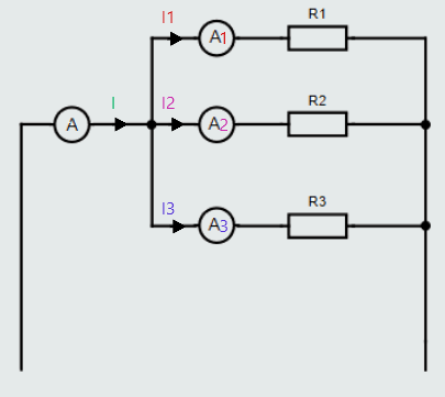
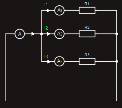
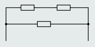
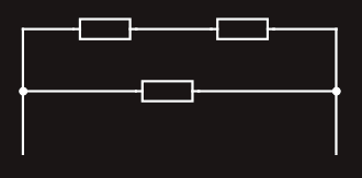
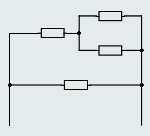
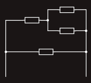
If we placed ammeters into a parallel circuit, as shown in figure on the right, we would find that the sum of the current readings in each branch would equal the current drawn from the supply.
As we have learned, this relationship was discovered by Kirchhoff, who realized that the sum of the currents approaching any junction in a circuit is equal to the sum of the currents leaving the same junction, and can be expressed as follows:
I = I1+I2+I3
And from Ohm's Law I = E/R, so:
E/RT = E/R1 + E/R2 + E/R3
Since the supply voltage E is common to each resistance, we can divide throughout by E, and we get:
1/RT = 1/R1 + 1/R2 + 1/R3
RT - total resistance of the circuit (is always less than the lowest-value branch resistance in any parallel circuit.)
So, for a parallel circuit, the total resistance is given by 1/RT = 1/R1 + 1/R2 + 1/R3.
We could also express this relationship in terms of conductance (G), expressed in siemens (S), as shown below. Conductance is simply the reciprocal of resistance.
GT = G1 + G2 + G3
There is a very useful ‘shortcut’ variation of the usual equation that we can use whenever we need to determine the equivalent resistance of two resistances. It’s called the ‘product over sum’ method, and is expressed as:
RT = (R1R2)/(R1+R2)
Parallel circuits in practice
Individual electrical components (lights, socket outlets, etc.) are all connected in parallel with each other to ensure that they share the same supply voltage. This is essential because for any component to operate at its rated power, it must be subjected to its rated voltage (which must correspond to the supply voltage). This is true whether we are looking at the wiring system of a house or the wiring system in a car. Each time another element is connected in parallel, there is less opposition to the flow of current through the entire circuit.
Series-parallel circuits
A series-parallel circuit is a circuit that combines the characteristics of series and parallel circuits. There is an infinite number of possible combinations but all such circuits can be solved by applying the same logical approach as it will be applied to the following examples.
Essentially, this approach comprises reducing any resistances connected in series to a single equivalent resistance, any resistances connected in parallel to a single equivalent resistance, . . . and continuing this process until we end up with a single resistance.
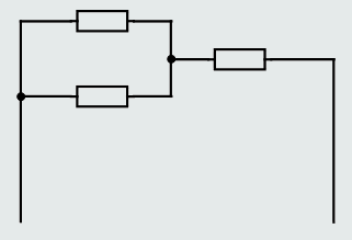
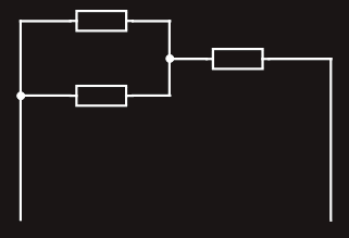
Examples of series-parallel circuits:
Solving series-parallel circuits
‘Solving’ a typical series-parallel circuit means that we must be able to:
(a) determine its total equivalent resistance
(b) determine the voltage drop across, and the current through, each component.
Determining the total equivalent resistance of a series-parallel circuit requires a logical step-by-step approach of solving parallel branches first (purely series parts to the parallel branches, first), then purely parallel branches into a single resistance and finally purely series branches into a total resistance of the circuit, and this procedure, of course cannot be developed instantly!
So, let's try this procedure on the following example:
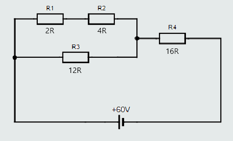
First, we should find if there are any parallel branches.
And the circuit has parallel branch consisting of resistances R1, R2 and R3.
Second, in that parallel branch, there is a purely series part consisting of R1 and R2, which should be solved first:
RA = R1+R2
RA = 2+4 = 6Ω
Now, we should solve parallel branch that consists of RA and R3:
RB = RAR3/(RA+R3)
RB = 6x12/(6+12) = 4Ω
Finally, there is only one branch, purely series, left consisting of RB and R4:
RT = RB+R4
RT = 4+16 = 20Ω
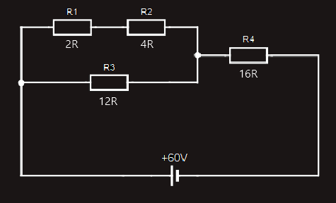
To determine the currents flowing through, and the voltage drops across, each of the components, we’ll start by redrawing the original circuit, and labelling all the voltage drops and currents:
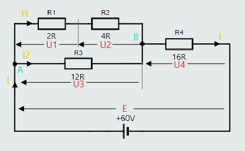
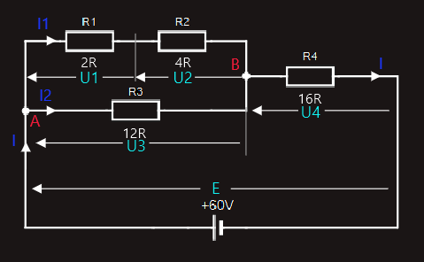
So, let’s examine the circuit. We’ve labelled the supply current I. In accordance with Kirchhoff’s Current Law, this current divides at point A in the circuit, with I1 flowing through the upper branch of the parallel combination, and I2 flowing through the lower branch. At point B, these two currents recombine and flow through R4 as the supply current, I.
As we have already worked out the total resistance of the circuit, we can find the value of the supply current:
I = E/RT
I = 60/20 = 3A
So, we can now easily find the voltage drop across R4, which is labelled U4:
U4 = R4xI = 16x3 = 48V
We know from Kirchhoff’s Voltage Law that in any closed loop, the sum of the individual voltage drops will equal the supply voltage. So, if we take the loop or path through R3 (i.e. the lower branch of the parallel combination) and R4, then:
E = U3+U4
U3 = E-U4 = 60-48 = 12V
We can now work out the value of the current I2, through the lower branch of the parallel combination:
I2 = U3/R3
I2 = 12/12 = 1A
If we apply Kirchhoff’s Current Law to junction A, we can find the value of current I1, flowing through the top branch of the parallel combination:
I = I1+I2
I1 = I-I2 = 3-1 = 2A
Finally, we are now able to determine the voltage drops U1 and U2:
U1 = R1xI1 = 2x2 = 4V
U2 = R2xI1 = 4x2 = 8V
So, solving a series-parallel circuit, regardless of its complexity, involves the logical, step-by-step approach demonstrated in the above example.
Voltage drops along cables
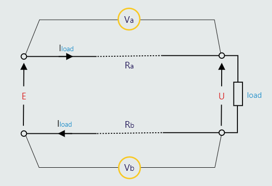
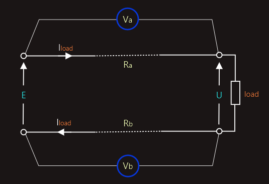
The lines that represent the connections (i.e. the ‘wires’) between components in the schematic diagrams are considered to have no resistance. But ‘real’ wires do have resistance. This means that, whenever a load current passes through a real wire or conductor, a voltage drop will occur along its length. So the potential difference appearing across the load must equal the supply voltage, less the voltage drop along the conductors supplying that load.
In the figure on the right the two voltmeters will measure the voltage drops along each of the two supply conductors.
This is a simple series circuit, in which the resistance of each conductor is in series with the resistance of the load. So the potential difference (U) appearing across the load will be the difference between the supply voltage (E) and the sum of the two voltage drops (voltmeter readings Va and Vb) along the two conductors:
U = E - (IloadRa + IloadRb)
U = E - Iload(Ra + Rb)
Normally, both conductors will have the same cross-sectional area and length and, so, will have identical resistances. So the above equation could then be simplified to:
U = E - 2(IloadR)
R - the resistance of either of the two conductors