


We can change the natural resistance of any circuit by using a circuit component called a resistor.
We can also use resistors to create useful circuits, such as a voltage divider.
A resistor is defined as ‘a passive electrical component, whose function is to limit the flow of electric current’.
Resistors may be fixed-value or variable-value.

Furthermore we have fixed-value resistors:
1. carbon composition
2. cracked carbon
3. metal film
4. wire wound
and variable-value resistors:
1. carbon composition
2. wire wound
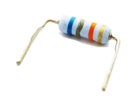
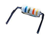
Variable resistors (variable-value resistors) are used when it is necessary to vary the value of the current in a circuit, or to vary the voltage across a circuit.
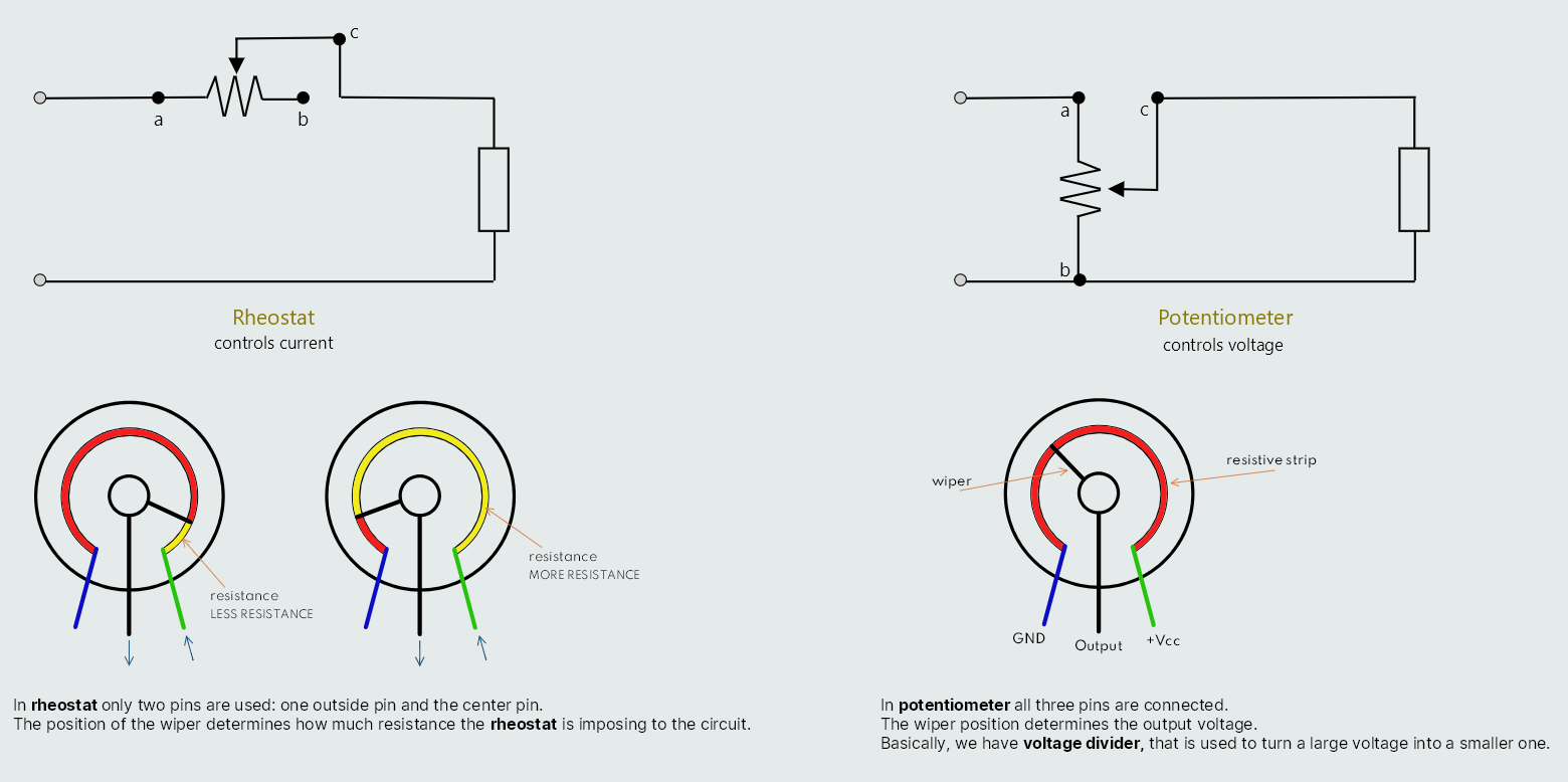
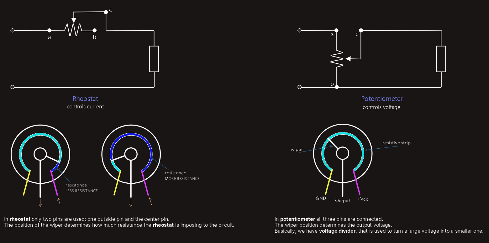
Rheostats and potentiometers
Variable resistors are frequently, but incorrectly, called either a ‘rheostat’ or a ‘potentiometer’. The terms rheostat and potentiometer, however, apply to their applications, and not to the devices themselves, as practically all variable resistors can be used either as a rheostat or as a potentiometer. A variable resistor connected as a rheostat is used to control current, while a variable resistor connected as a potentiometer is used to control voltage. These resistors have three terminals: one at opposite ends of the winding (a and b), and the third connected to the ‘brush’ or wiper (c). When used as a rheostat, one of the fixed terminals and the wiper terminal are used; when used as a potentiometer, all three terminals are used.
There are also other types of resistors – including those whose resistance are affected by light, temperature, etc. Photoresistors are resistors whose resistance varies with the intensity of the light falling on them, thermistors are resistors whose resistance varies with temperature; resistors whose resistance increases with an increase in temperature are termed positive temperature coefficient (PTC) resistors, while those whose resistance falls with an increase in temperature are termed negative temperature coefficient (NTC) resistors.
Whenever we select a resistor, not only must we take the value of its resistance into account, but we must also consider its power rating – i.e. the rate at which it can dissipate energy through heat transfer into the surroundings by radiation, convection and conduction. It is its power rating that determines the maximum continuous current a resistor can handle without becoming damaged through overheating.
Since a physically larger resistor has a greater surface area than a physically smaller resistor, it can dissipate energy at a greater rate. The physical size of a resistor, therefore, is indicative of its power rating, but not of its resistance.
The resistance of a resistor cannot be ‘estimated’ from its physical size, but must be determined from its color code.
There are two systems for identifying the resistance of a resistor:
1. color code
2. alpha-numeric code
The most-common system for identifying the resistance of a fixed-value resistor is termed the ‘colored band’ method, while alpha-numeric code uses a combination of letters and numerals to identify resistance values.
Conductors and cables
In the electrotechnology industry, ‘wires’ are more-properly called ‘conductors’. A conductor may be solid or stranded, insulated or uninsulated. An electric cable normally consists of one or more metal current-carrying conductors, each surrounded by a layer of insulation which, in turn, is usually covered by a tough outer protective sheath. In some cases, the cable may be further protected by metal tape or wire armour.
Conductors
As we have said, in the electrotechnology industry, ‘wires’ are more-properly called ‘conductors’. A cable may have one, two, three or more separately insulated conductors. Each insulated conductor is called a core, and cables with more than one core are referred to as multicore cables.
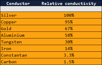
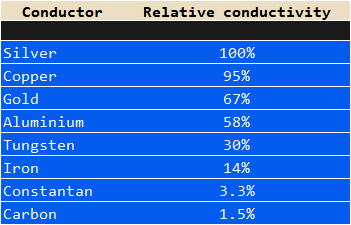
The very best metal conductor is silver which, because of its cost, is limited to special applications such as relay contacts, printed circuit boards, etc. It’s common to compare the conductivity of other conductors to that of silver.
The most widely used conductor is copper, which has a number of advantages over its nearest rival, aluminium. Copper is second only to silver in terms of its relative conductivity (95%), and is a readily available natural resource.
The abundance of aluminium makes it a more economical alternative to copper, and is the second most widely used conductor. Its conductivity, relative to silver, is 58 per cent, making it a poorer conductor than copper which means it must have a larger cross-sectional area than copper in order to conduct the same amount of current.
The central component of any cable is the conductor itself, which may be solid, or stranded.
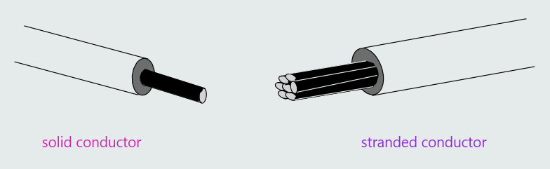
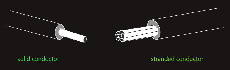
Cables of the type used to wire residential and commercial buildings, having cross-sectional areas below 4 mm2, are usually manufactured using solid conductors. Beyond this cross-sectional area, conductors are normally stranded. Stranded conductors impart greater flexibility into cables, compared with cables having solid conductors of equivalent size, making them much easier to handle.
A conductor of any given cross-sectional area can be manufactured either from a few strands of thicker wire, or from a large number of strands of thinner wire – in either case, the total area will remain the same. Generally, for any given cross-sectional area, the greater the number of strands, the greater the flexibility of the cable. This is why ‘flexible cables’ (commonly called ‘flex’ or ‘cords’) are used to connect portable appliances to the fixed wiring in buildings. Flexible cables enable such appliances to be regularly moved around without over-stressing and, possibly, snapping the conductors.
Insulation
A cable’s insulation is the layer of dielectric material immediately surrounding the conductor(s), whose function it is to electrically isolate the conductors from each other as well as from their surroundings, in order to prevent short circuits or anyone from receiving an electric shock by accidentally touching them. The material used as an insulator or dielectric must have each of the following properties:
• high resistivity
• high dielectric strength
• impervious to moisture
• strength and toughness
• flexibility
• immune to chemicals
• stability over a wide range of operating temperatures
The type of insulating (or ‘dielectric’) material determines the safe operating temperature of a conductor (for residential wiring, typically 70°C or 90°C), as early insulation failure may result if its actual temperature is allowed to exceed its specified safe operating temperature.
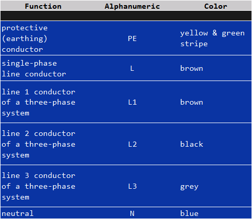
Insulation is always color coded so that the function of each conductor can be identified.
These colors must conform to national or international codes of practice.
For example, the approved colors for identifying cable cores in Europe for a.c. power and lighting circuits are shown in the table on the right, while in North America, the colors are different from those used in Europe. Those specified by the National Electrical Code (United States) differ slightly from those specified by the Canadian National Code.
Cables used in residential installation work will normally have a thermoplastic sheath, as the likelihood of mechanical damage is low because such cables are normally reasonably-protected from their surroundings by being run below floorboards, sunk into plasterwork, etc. The main functions of this sheath are to provide limited mechanical protection to the insulation, to prevent ingress of moisture into the cable and, in the case of multicore cables, to contain the individual cores.
Cables, particularly underground distribution cables, intended for use where the possiblity of mechanical damage is high, require additional protection. Such cables are usually armoured. This consists either of overlapping flat metal tapes or of circularsection metal wires (often two layers, wound in opposite directions to increase the cable’s flexibility), manufactured from steel or, in some cases, aluminium.

Armouring is intended to protect the cable from the impact of hand tools such as shovels, pick axes etc., and to prevent the possibility of penetration by rocks etc., once the cable trench has been backfilled.
Ohm's Law of constant proportionality
Relationship between resistance, voltage and current
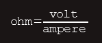
We learnt earlier that the ohm is defined as electrical resistance between two points along a conductor such that, when a potential difference of one volt is applied between those points, a current of one ampere results.
In other words, an ohm is equivalent to a volt per ampere: 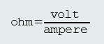
 Rewriting this equation in terms of quantities, rather than of units:
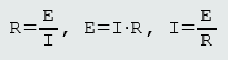
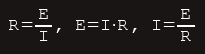 These three equations are the most fundamental and, certainly, amongst the most important equations in electrical engineering showing the relationship between the three fundamental quantities: potential difference (E), current (I) and resistance (R).
It’s very important to understand that equation for resistance simply tells us what the resistance happens to be for any particular ratio of voltage to current. This ratio does not determine the resistance. Resistance, as we learnt earlier, is determined by a conductor’s length, cross-sectional area and resistivity (which, in turn, is affected by temperature) – it is not directly affected by either voltage or current.