Three-Phase Circuits
Most of the electrical power generated in the world today is three-phase. Three-phase power was first conceived by Nikola Tesla. In the early days of electric power generation, Tesla not only led the battle concerning whether low-voltage direct current or high-voltage alternating current should be appropriate, but he also proved that three-phase power was the most efficient way that electricity could be produced, transmitted, and consumed.
There are several reasons why three-phase power is superior to single-phase power. 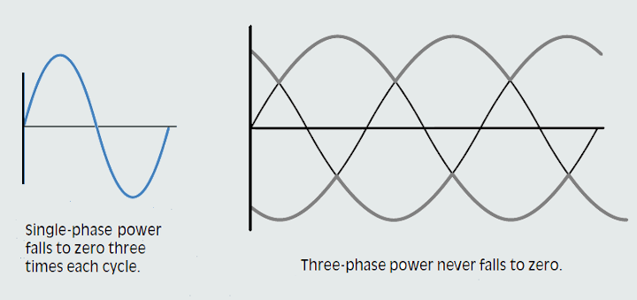
 1. The horsepower rating of three-phase motors and the KVA rating of three-phase transformers is about 150% greater than for single-phase motors or transformers with a similar frame size.
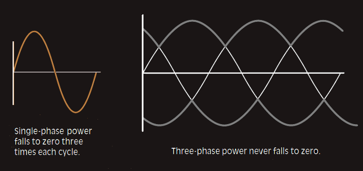
2. The power delivered by a single-phase system pulsates; the power falls to zero three times during each cycle. The power delivered by a three-phase circuit pulsates also, but it never falls to zero. In a three-phase system, the power delivered to the load is the same at any instant. This produces superior operating characteristics for three-phase motors.
3. In a balanced three-phase system, the conductors need to be only about 75% the size of conductors for a single-phase two-wire system of the same KVA rating. This helps offset the cost of supplying the third conductor required by three-phase systems.
In order to understand the reasons for, and the method of generating a three-phase supply, let us consider the generation of a single-phase supply, first. Alternating voltage is provided by an a.c. generator, more commonly called an alternator.
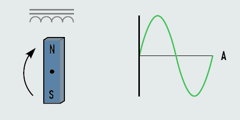
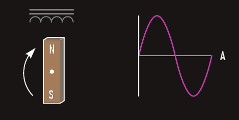
It was already shown that when a coil of wire, wound on to a rectangular former, is rotated in a magnetic field, an alternating (sinusoidal) voltage is induced into the coil. Since it is the relative movement between conductor and magnetic flux that matters, it is not important whether the field is static and the conductor moves, or vice versa.
For a practical alternator it is found to be more convenient to rotate the magnetic field, and to keep the conductors (coil or winding) stationary.
In any rotating a.c. machine, the rotating part is called the rotor, and the stationary part is called the stator. Thus, in an alternator, the field system is contained in the rotor. The winding in which the emf is generated is contained in the stator.
The term field refers to the magnetic field. This field is normally produced by passing d.c. current through the rotor winding. Since the winding is rotated, the current is passed to it via copper slip-rings on the shaft. The external d.c. supply is connected to the slip-rings by a pair of carbon brushes.
For very small alternators, the rotor would contain permanent magnets to provide the rotating field system. This then altogether eliminates the need for any slip-rings.
A single-phase alternating voltage can be produced by rotating a magnetic field through the conductors of a stationary coil. The induced voltage will change polarity at the same speed as the rotation of the magnetic field.
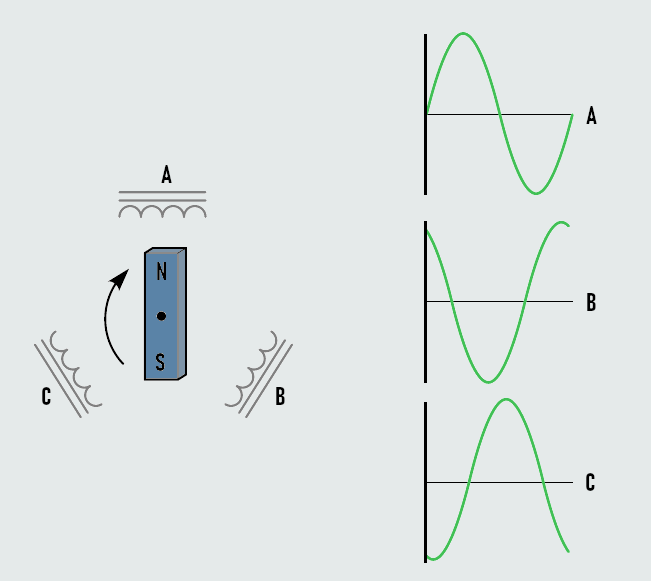
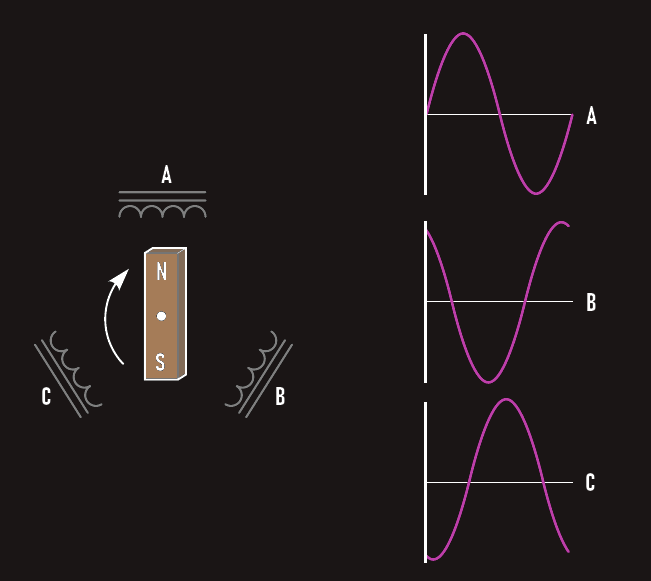
If three separate coils are spaced 120° apart, three voltages 120° out of phase with each other will be produced when the magnetic field cuts through the coils. This is the manner in which a three-phase voltage is produced.
There are two basic three-phase connections, the wye or star connection and the delta connection.
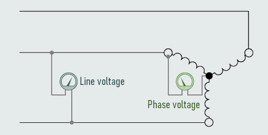
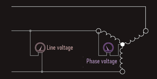
Star connection
The wye or star connection is made by connecting one end of each of the three-phase windings together. The voltage measured across a single winding or phase is known as the phase voltage, the voltage measured between the lines is known as the line-to-line voltage or simply as the line voltage.
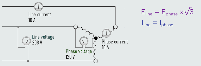
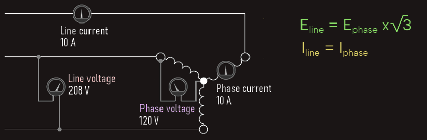
Ammeters have been placed in the phase winding of a wye-connected load and in the line supplying power to the load. Voltmeters have been connected across the input to the load and across the phase. A line voltage of 208 V has been applied to the load. We can notice that the voltmeter connected across the lines indicates a value of 208 V, but the voltmeter connected across the phase indicates a value of 120 V. In a wye-connected system, the line voltage is higher than the phase voltage by a factor of the square root of 3 (1.732). Also we can notice that 10 A of current flows in both the phase and the line. In a wye-connected system, phase current and line current are the same.
Voltage relationships in a star connection
Looking at first, we can ask ourselves why the line voltage of the wye connection used in above illustration is 208 V instead of 240 V?
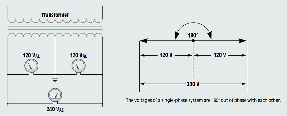
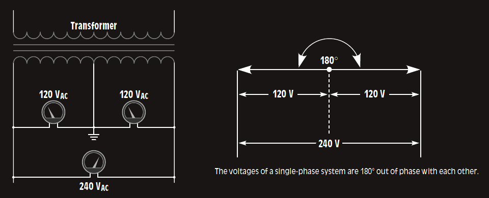
Since line voltage is measured across two phases that have a value of 120 V each, it would appear that the sum of the two voltages should be 240 V. One cause of this misconception is that many of us are familiar with the 240/120 V connection supplied to most homes. If voltage is measured across the two incoming lines, a voltage of 240 V will be seen. If voltage is measured from either of the two lines to the neutral, a voltage of 120 V will be seen. The reason for this is that this is a single-phase connection derived from the center tap of a transformer. If the center tap is used as a common point, the two line voltages on either side of it will be 180° apart and opposite in polarity. The vector sum of these two voltages would be 240 V.