


We have mentioned that the magnet is removed at the same rate as it was inserted; then the magnitudes of the deflections will be the same. When the magnet is moved at different speeds into and out of the coil and the resulting magnitudes of the galvanometer deflection noted, it will be found that the faster the movement, the greater the induced emf.
This can be further extended in three ways. If the magnet is replaced by a more powerful one, it will be found that for the same speed of movement, the corresponding emf will be greater. Similarly, if the coil is replaced with one having more turns, then for a given magnet and speed of movement, the value of the emf will again be found to be greater. Finally, if the magnet is held stationary within the coil, and the coil is then moved away, it will be found that an emf is once more induced in the coil. The emf has the same polarity as obtained when the magnet was first inserted into the stationary coil.
This last effect illustrates the point that it is the relative movement between the coil and the flux that induces the emf.
Under controlled conditions, this experimental procedure would give us following results:
The magnitude of the induced emf is directly proportional to the value of magnetic flux, the rate at which this flux links with the coil, and the number of turns on the coil.
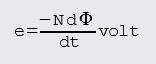
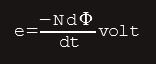
1. Lower-case letter e is because it is only present for the short interval of time during which there is relative movement taking place, and so has only a momentary value.
2. The term dφ/dt is mathematical means of stating ‘the rate of change of flux with time’. The combination Ndφ/dt is often referred to as the ‘rate of change of flux linkages’.
3. The minus sign is a reminder that Lenz’s law applies.
Lenz’s law states that the polarity of an induced emf is always such that it opposes the change which produced it. This is similar to the statement in mechanics, that for every force there is an opposite reaction.
4. Equation above forms the basis for the definition of the unit of magnetic flux, the weber.
The weber is that magnetic flux which, linking a circuit of one turn, induces in it an emf of one volt when the flux is reduced to zero at a uniform rate in one second.
1 volt = 1 weber/second or 1 weber = 1 volt second.
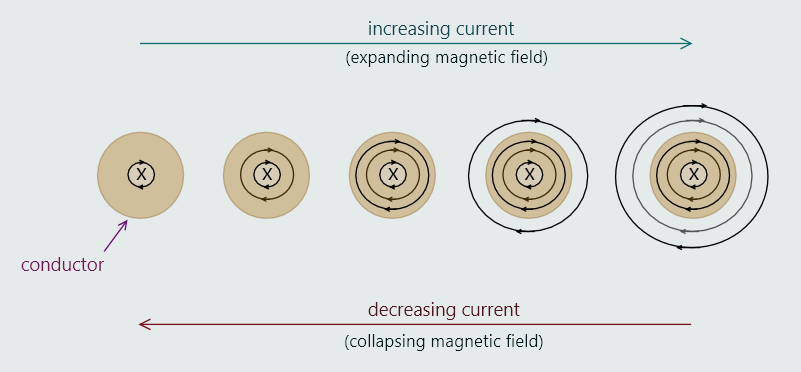
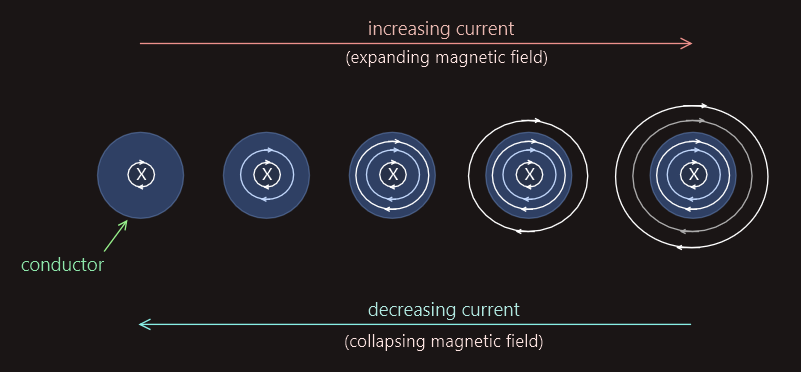
Electric current is always sorrrounded by a magnetic field and the 'direction' of magnetic field depends upon direction of the current. Magnetic field exists whether or not the conductor is present; i.e. magnetic field will also sorround an arc, which is current passing through air or vacuum.
When the current is initially switched on, it starts to rapidly increase from zero to a maximum value, limited by the resistance of the circuit. During this time, the field actually starts expanding from within the conductor itself, as illustrated on the right. This process repeats itself, until the expanding circular magnetic fields start to surround the conductor externally, and it continues until the current has reached its maximum value, at which point the field becomes constant.
When the current is switched off, this process reverses itself, as the tension within each circular magnetic field causes them all to collapse inwards.
The action of these expanding and collapsing concentric magnetic field rings, ‘cutting’ the conductor internally, is partially responsible for the ‘skin effect’ described earlier.
It is standard practice to show the flux as concentric circles, but actually they are three-dimensional and enclose the current along its entire path throughout a circuit. So, it is more accurate to think of them as concentric tubes, rather than as concentric circles.
The direction of the magnetic field is clockwise for current drifting away from us, and counterclockwise for current drifting towards us.
We could use alternative rules in this context, to easier remember magnetic field direction.
The first is called the ‘corkscrew rule’. With this rule, the direction of the field is the same direction in which a corkscrew is turned, when pointing in the same direction as conventional current. An alternative rule for determining the direction of flux around a current is the ‘right-hand grip rule’. If we grip a conductor, with our thumb pointing in the direction of conventional current, then the ‘curl’ of our fingers will represent the direction of the field.
If a length of current-carrying conductor is twisted to form a single loop, then the resulting magnetic flux lines would appear like illustrated below; and if an insulated conductor is wound to form several loops, then it will form a coil. When a current passes through a coil, the magnetic field surrounding each individual loop acts to reinforce those around adjacent loops to form a single, strong magnetic field.
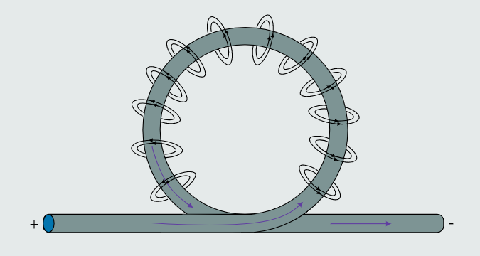
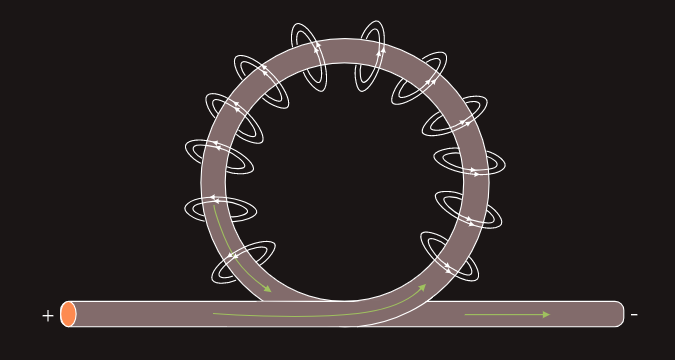
The shape of the magnetic field surrounding a current-carrying coil closely resembles the field surrounding a bar magnet, with its poles concentrated towards opposite ends of the coil.
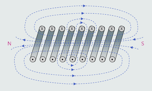
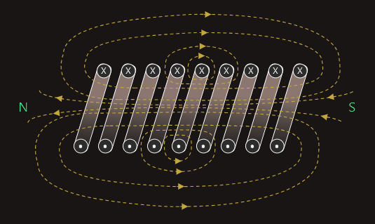
The polarity of each end of a coil may be determined using a variation of the ‘right-hand grip rule’. In this case, we would simply grasp the coil with our right hand, such that the curl of the fingers represents the direction of (conventional) current around the coil, and the thumb will then point towards the north pole end of the coil. The opposite end will then be its south pole.
Magnetic flux density
We have learned that magnetic fields are represented by imaginary lines of magnetic flux (Φ). Although these lines are imaginary, we can still quantify them; the SI unit of measurement is weber (Wb). The ‘closeness’ of a field’s lines of magnetic flux indicates the intensity of that field at any given point, which is termed magnetic flux density (B) of the field at that particular point, measured in tesla (T). Just as with a permanent magnet, the flux density is always greatest in the areas nearest the poles of the coil.
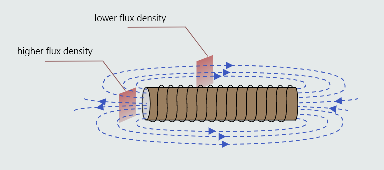
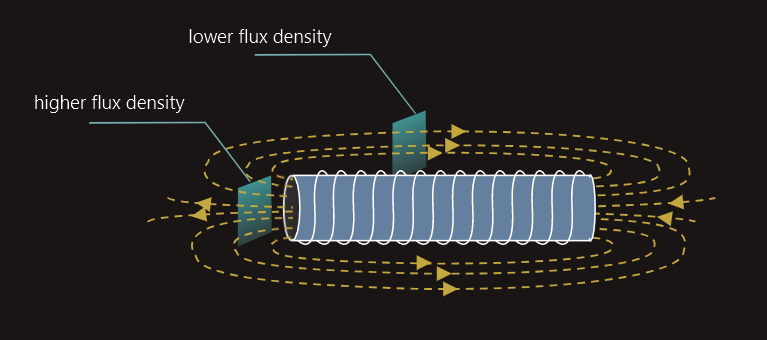
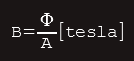
We can see that more lines of flux pass through the shaded rectangle near the poles, than through the rectangle of identical cross-sectional area placed midway along the coil. Flux density is defined as the ‘flux per unit area’: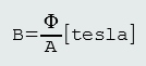
 • B - flux density (T)
• Φ - flux (Wb)
• A - area (m2)
Example:
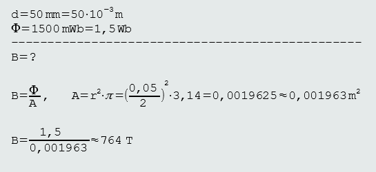
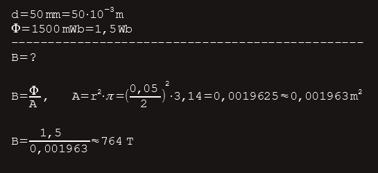
A current-carrying coil of inside diameter 50 mm generates 1500 mWb of magnetic flux. Calculate the flux density within the coil.
Solution:
Electromagnets
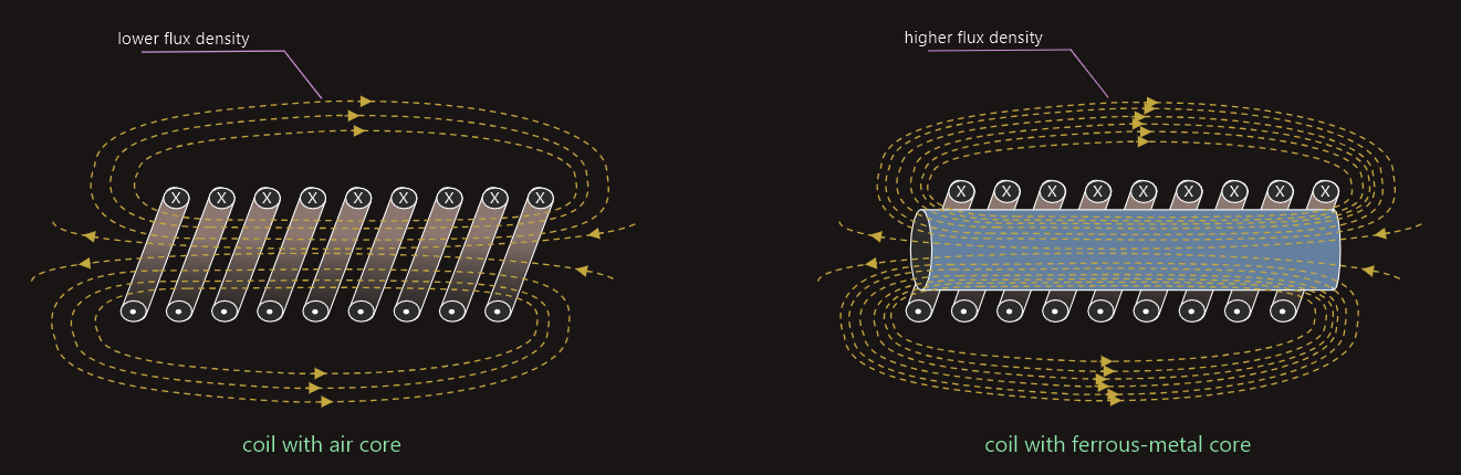
The flux density of the magnetic field produced by a coil can be significantly (hundreds or even thousands of times) increased by winding the coil around a ferromagnetic (iron alloy) core, rather than around a hollow tube shown earlier.
This was explained by the Scottish engineer and academic Sir James Ewing (1855–1935) as follows: when the core is magnetized, the individual magnetic field of each of its millions of domains align with and, therefore, reinforce the relatively weak magnetic field due to the current alone, thus creating a very strong combined field.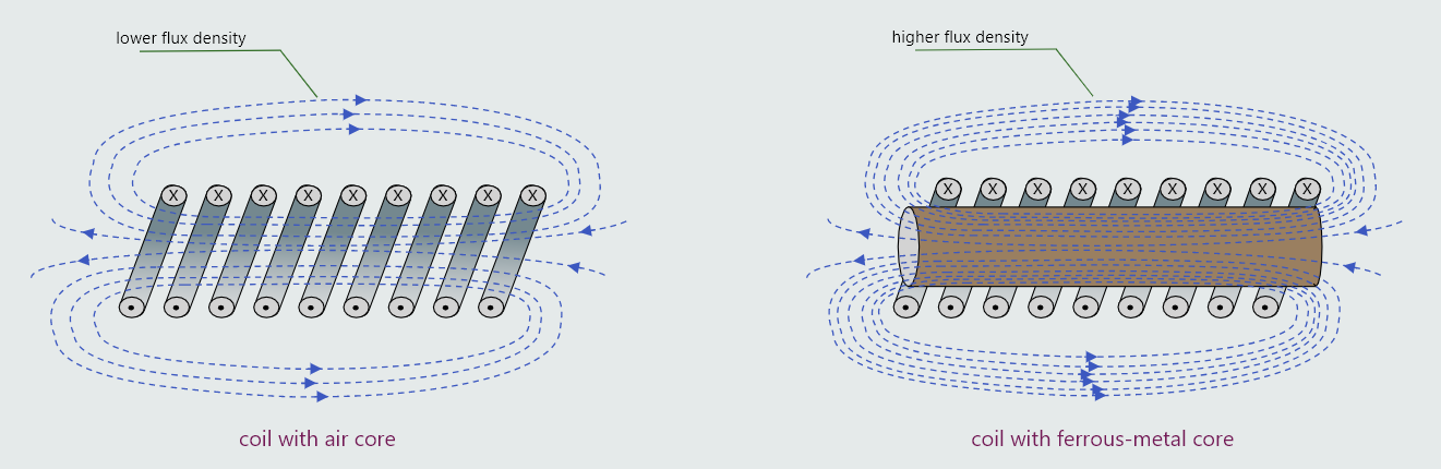
 Electromagnets are very much stronger than the strongest permanent magnet, and are used whenever we want to use electric current to create movement, such as in circuit breakers, motor starters, relays, etc.