


Electric flux and flux density
In the SI system one ‘line’ of flux is assumed to radiate from the surface of a positive charge of one coulomb and terminate at the surface of a negative charge of one coulomb. Hence the electric flux has the same numerical value as the charge that produces it. Therefore the coulomb is used as the unit of electric flux, and the Greek letter Ψ is usually replaced by the symbol for charge Q.
The electric flux density D is defined as the amount of flux per square metre of the electric field. This area is measured at right angles to the lines of force.
Example:
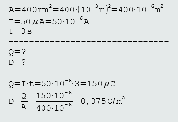
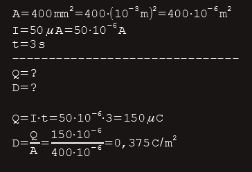
Two parallel metal plates, each having a csa of 400 mm2, are charged from a constant current source of 50 µA for a time of 3 seconds. Calculate (a) the charge on the plates, and (b) the density of the electric field between them.
Solution:
The charging process
Consider a pair of parallel, initially uncharged plates that can be connected to a battery via a switch. The number of electrons and protons shown for each plate are for demonstration purposes and are not representative of the actual numbers involved. They are shown to help us explain the charging process that will take place when the switch is closed.
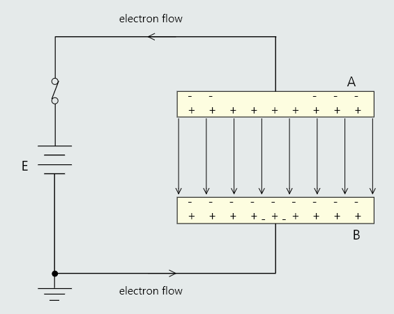
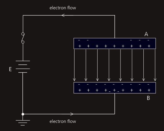
On closing the switch, some electrons from plate A will be attracted to the positive terminal of the battery. In this case, since plate A has lost electrons it will acquire a positive charge. This results in an electric field radiating out from plate A. The effect of this field is to induce a negative charge on the top surface of plate B, by attracting electrons in the plate towards this surface. Consequently, the lower surface of plate B must have a positive charge. This in turn will attract electrons from the negative terminal of the battery. Thus for every electron that is removed from plate A one is transferred to plate B. The two plates will therefore become equally but oppositely charged.
This charging process will not carry on indefinitely. Actually, it will last for only a very short space of time. This is because as the charge on the plates increases so too does the voltage developed between them. Thus the charging process continues only until the p.d. between the plates, V is equal to the emf, E of the battery. The charging current at this time will become zero because plates A and B are positive and negative respectively.
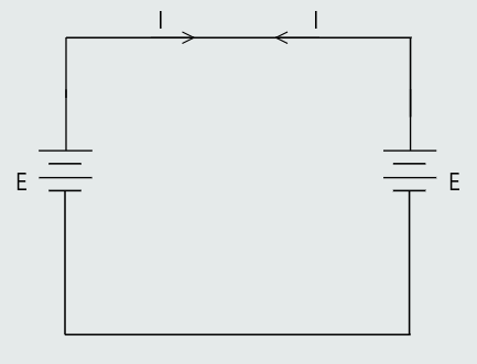
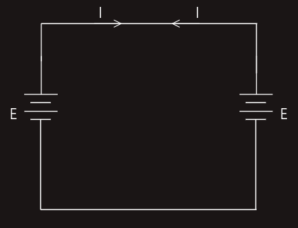
This circuit is equivalent to two batteries of equal emf connected in parallel as shown in figure on the right. In this case each battery would be trying to drive an equal value of current around the circuit, but in opposite directions. Hence the two batteries ‘balance out’ each other, and no current will flow.
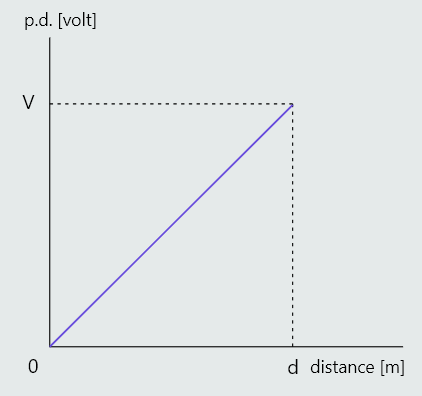
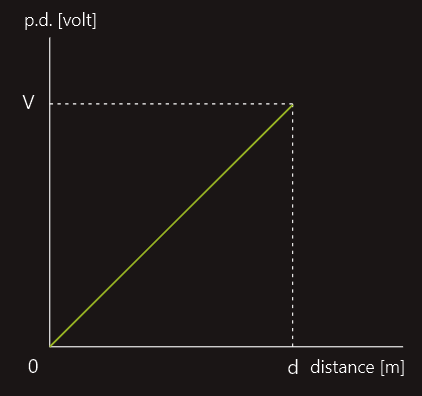
With suitable instrumentation it would be possible to measure the p.d. between plate B and any point in the dielectric. If this was done, then a graph of the voltage versus distance from B would look like that in the figure below. The slope of this graph is uniform and has units of volts/metre i.e. the units of potential gradient,  .
.
We would see in detail analysis that 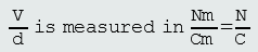 , that is exactly the same as for electric field strength.
Since electric field strength is defined in terms of the ratio of the force exerted on a charge to the value of the charge, which is an extremely difficult to measure, and because the p.d. and distance between the charged plates is a very simple matter to measure, for practical purposes, electric field strength is quoted in the units volt/metre, 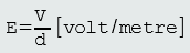 .
.
Capacitance
In order for one plate to be at a different potential to the other one there is a need for a charge. This requirement is known as the capacity of the system. For a given system the ratio of the charge required to achieve a given p.d. is a constant for that system. This is called the capacitance (C) of the system, 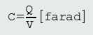 .
.
Unit for capacitance, farad (F) is defined as the capacitance of a system that requires a charge of one coulomb in order to raise its potential by one volt. The farad is a very large unit, so in practice it is more usual to express capacitance values in microfarads (µF), nanofarads (nF), or picofarads (pF).
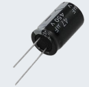
Capacitors
A capacitor is an electrical component that is designed to have a specified value of capacitance. In its simplest form it consists of two parallel plates separated by a dielectric; i.e. exactly the system we have been dealing with earlier.
In order to be able to design a capacitor we need to know what dimensions are required for the plates, the thickness of the dielectric (the distance of separation d), and the other properties of the dielectric material chosen.
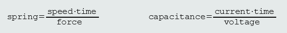
Physical equivalent to the capacitor is a spring.
A spring has the capacity to store energy. When a force is applied, it will hold that energy until it is released. Capacitance is similar to the elasticity of the spring. (The spring constant is the inverse of the elasticity.)

When an electric field exists in a vacuum, the ratio of the electric flux density to the electric field strength is a constant, known as the permittivity of free space, ε0=8.854x10⁻¹² F/m. Since a vacuum is a well defined condition, the permittivity of free space is chosen as the reference value from which the permittivity of all other dielectrics are measured. This is a similar principle to using Earth potential as the reference for measuring voltages.
The capacitance of two plates will be increased if, instead of a vacuum between the plates, some other dielectric is used. This difference in capacitance for different dielectrics is accounted for by the relative permittivity of each dielectric. Thus relative permittivity is defined as the ratio of the capacitance with that dielectric to the capacitance with a vacuum dielectric, εr=C2/C1.
• C1 - capacitance with a vacuum
• C2 - capacitance with the other dielectric
Relative permittivity for air dielectrics is 1, because dry air has the same effect as a vacuum.
For a given system the ratio of the electric flux density to the electric field strength (D/E) is a constant, known as the absolute permittivity of the dielectric being used. Dielectric (other than air) is more effective than a vacuum by a factor of εr times, so the absolute permittivity is given by ε=ε0‧εr F/m.
When a capacitor is connected to a battery, electrons redistribute themselves from the positive side of the capacitor to the negative side. This means that the negative side of the capacitor is negatively charged and the positive side of the capacitor is positively charged. This process is known as 'charging the capacitor', and eventually the capacitor becomes fully charged. The electrical charge imbalance that has built up on the capacitor has created its own voltage, and the voltage of the battery no longer has the strength to overcome it. The battery cannot shuffle any more electrons around on the capacitor. At this point we can disconnect the battery from the capacitor. But when we do, the electrons on the capacitor plates stay put. The electrons on the negative plate want desperately to rejoin with their holes left on the positive plate, but the dielectric separating them makes that very difficult to do. There’s no path to rejoin. Instead, the separated charge has created a voltage across the two terminals of the capacitor. The charged capacitor is much like battery in that it has a voltage across the two terminals and can act as a current source. However, the capacitor has no way to sustain this voltage once the electrons begin to flow and leave the negative terminal. The capacitor discharges rapidly, the voltage drops, and eventually the capacitor is completely discharged. Undisturbed, though, the capacitor ideally will store its charge forever, but no capacitor is perfect, however, and over time some of the charge leaks out due to the parasitic resistance of the insulation materials used in the capacitors construction. The amount of charge a capacitor can hold is measured by its capacitance, and the unit of capacitance is the farad (F).