Since much of the capacitor’s energy is stored in the dielectric, the type of dielectric used is extremely important in determining the amount of capacitance a capacitor will have. Different materials are assigned a number called the dielectric constant. Vacuum is assigned the number 1 and is used as a reference, while air has a dielectric constant of approximately 1.0006.
The basic unit of capacitance is the farad, symbolized by the letter F. It receives its name from a famous scientist named Michael Faraday.
Q=C·V
Connecting capacitors in parallel has the same effect as increasing the plate area of one capacitor. For example, three capacitors connected in parallel have total capacitance: CT=C1+C2+C3.
Connecting capacitors in series has the effect of increasing the distance between the plates, thus reducing the total capacitance of the circuit: 1/CT=1/C1+1/C2+1/C3.
Capacitive Charge and Discharge Rates
Capacitors charge and discharge at an exponential rate. A charge and discharge curves for a capacitor are shown in figures below. 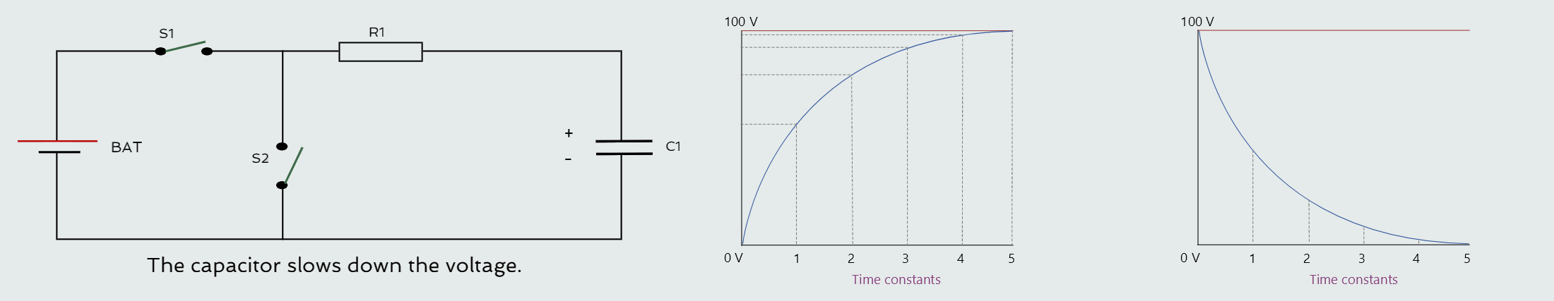
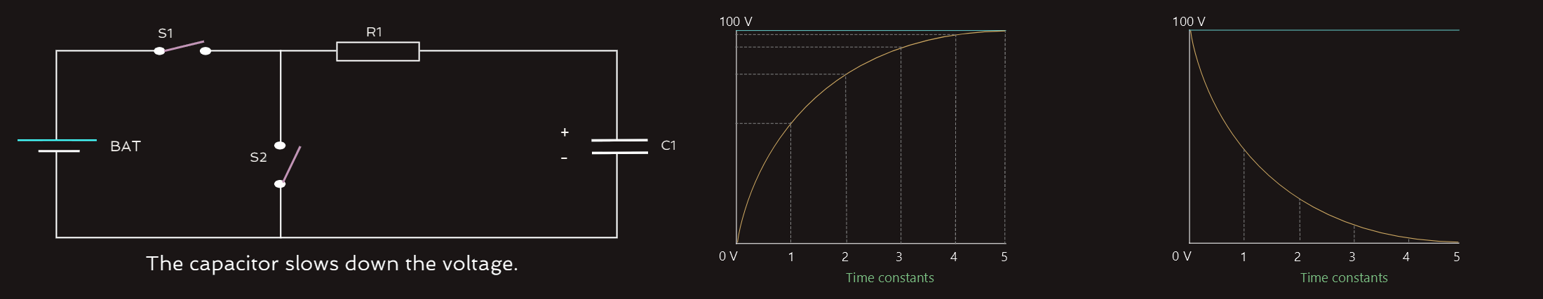 The curve is divided into five time constants, and during each time constant the voltage changes by an amount equal to the same percentage of the maximum amount that it can change (voltage increases from 0V to 100V and decreases from 100V to 0V by the same percentage number).
The charge time of the capacitor can be determined very accurately when a capacitor is connected in a circuit with a resistor - RC time constant.
τ=RxC
• τ - time for one time constant (sec.)
• R - resistance (ohms)
• C - capacitance (farads)
Capacitors are among the most used of electric components. They are used for power factor correction in industrial applications, in the start windings of many single-phase AC motors, to produce phase shifts for SCR and Triac circuits, to filter pulsating DC, and in RC timing circuits. Capacitors are used extensively in electronic circuits for control of frequency and pulse generation. The type of capacitor used is dictated by the circuit application.
We have said earlier that capacitors impede a change in voltage and the capacitor will let current change 'all it wants'. Furthermore, for AC sources current and voltage are always changing. How fast they change is a function of a term known as frequency. Frequency is the number of cycles of change per second; with the unit hertz. The higher the frequency, the faster the change in voltage and current. So, capacitor will block currents that have zero frequency (like a DC battery) and pass currents that change. In other words, capacitor is an infinite resistor at DC or zero frequency. As frequency increases, the “resistance” (reactance) of the capacitor gets lower and lower, approaching zero. This capacitive reactance is known as XC, expressed with the following equation with the unit ohms.
XC=1/(2π·f·C)
We see that the higher the frequency, the easier the current will pass through a capacitor.
When both voltage and current are in sync, they are in phase and there is no phase shift.
Capacitors impede a change in voltage, but current is not affected and in relationship graph between voltage and current we would see that the voltage is delayed relative to the current; from the voltage point of view it looks like the current is changing first.
Capacitors and inductors are components that impede a signal, the amount of which depends on the frequency of the signal. The capacitor delays voltage changes; it blocks lower frequencies while letting higher ones through.
Inductors
Inductor opposes a change of current.
Some amount of inductance is present in all AC circuits because of the continually changing magnetic field. But, because of its small amount of a single conductor in most instances, it is not considered in circuit calculations. Circuits are generally considered to contain inductance when any type of load that contains a coil is used.
1. When magnetic lines of flux cut through a coil, a voltage is induced in the coil.
2. An induced voltage is always opposite in polarity to the applied voltage (it limits the flow of current through the circuit).
3. The amount of induced voltage is proportional to the rate of change of current.
4. An inductor opposes a change of current.
So, inductors impede a change in current and inductor will let voltage change 'all it wants'. Inductor is just the opposite of the capacitor explained above; it starts with 0 Ω of resistance at a zero frequency and then increases to infinity along with the frequency. Inductive reactance XL is expressed as following:
XL=2π·f·L
The higher the frequency, the harder it becomes for the current to get through an inductor.
Inductors impede a change in current, but voltage is not affected, so if we graph the relationship between voltage and current, we will see that the change in current is a little out of sync with the change in voltage. It is said to be lagging behind.
Inductors and capacitors are components that impede a signal, the amount of which depends on the frequency of the signal. The inductor delays current changes; it passes lower frequencies while blocking higher ones.
Capacitors and inductors are opposite in the way they react to the frequency of a signal.
When inductors are connected in series, the total inductance of the circuit equals the sum of the inductances of all the inductors: LT=L1+L2+L3.
When inductors are connected in parallel, the reciprocal of the total inductance is equal to the sum of the reciprocals of all the inductors: 1/LT=1/L1+1/L2+1/L3.
It was stated before that one of the basic laws of electricity is that whenever current flows through a conductor, a magnetic field is created around the conductor. The direction of the current flow determines the polarity of the magnetic field, and the amount of current determines the strength of the magnetic field.
This basic law in reverse is the principle of electromagnetic induction, which states that whenever a conductor cuts through magnetic lines of flux, a voltage is induced into the conductor.
The important factors concerning electromagnetic induction are a conductor, a magnetic field, and relative motion. In practice, it is often desirable to move the magnet instead of the conductor. Most AC generators or alternators operate on this principle.
A simple one-loop generator is shown in figure below, on the left. The loop is attached to a rod that is free to rotate. This assembly is suspended between the poles of two stationary magnets. If the loop is turned, the conductor cuts through magnetic lines of flux and a voltage is induced into the conductor. If the speed of rotation is increased, the conductor cuts more lines of flux per second and the amount of induced voltage increases. If the speed of rotation remains constant and the strength of the magnetic field is increased, there will be more lines of flux per square metre. When there are more lines of flux, the number of lines cut per second increases and the induced voltage increases. 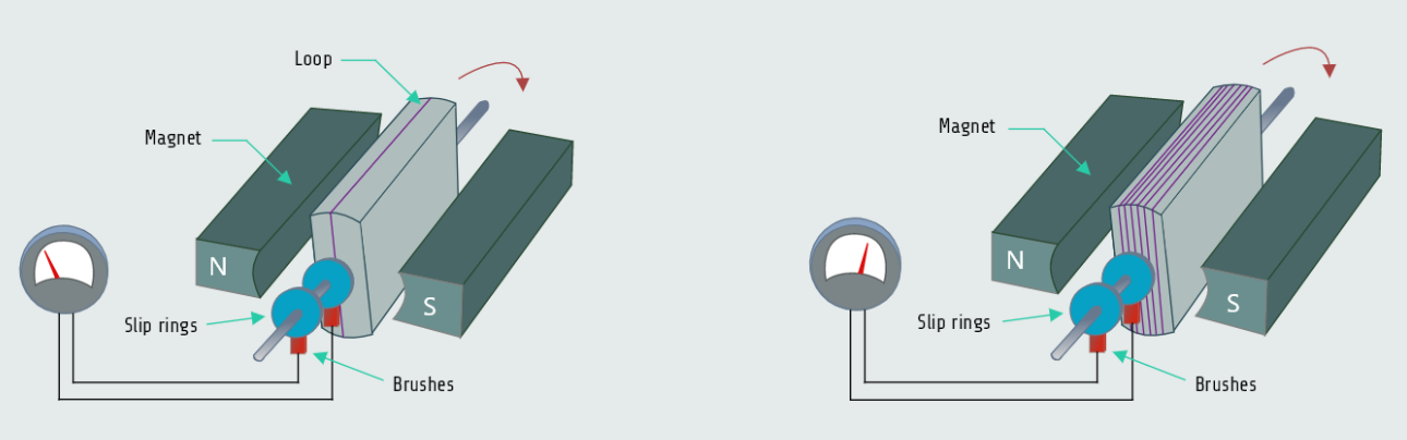
 On the above right figure more turns of wire are added to the loop, more flux lines are cut per second and the amount of induced voltage increases again. Adding more turns has the effect of connecting single conductors in series, and the amount of induced voltage in each conductor adds.
The Exponential Curve
When a resistive load is connected to a source of DC, the current instantly rises to its maximum value. The resistor for example has a value of 10 ohms and is connected to a 20 volt source. When the switch is closed, the current instantly rises to a value of 2 amperes.
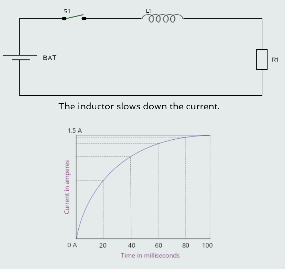
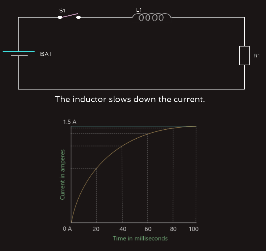
If we replace the resistor with an inductor that has a wire resistance of 10 ohms and the switch is closed, the current cannot instantly rise to its maximum value of 2 amperes.
As current begins to flow through an inductor, the expanding magnetic field cuts through the conductors, inducing a voltage into them. According to Lenz’s law, the induced voltage is opposite in polarity to the applied voltage. The induced voltage, therefore, acts like a resistance to hinder the flow of current through the inductor.
The induced voltage is proportional to the rate of change of current. When the switch is first closed, current flow through the coil tries to rise instantly. This extremely fast rate of current change induces maximum voltage in the coil. As the current flow approaches its maximum Ohm’s law value of 2 amperes in this example, the rate of change becomes less and the amount of induced voltage decreases.
The exponential curve is divided into five time constants. During each time constant, the current rises an amount equal to 63.2% of some value (for example 1.5 amperes in 100 milliseconds). So, each time constant is 20 ms and the current increases at a rate of 63.2% during each time constant. During the first time constant, the current rises from 0 to 63.2% of its total value, or 0.984 ampere. The remaining current is now 0.552 ampere; during the second time constant, the current rises 63.2% of the remaining value or 0.349 ampere and so on..., until the current has reached approximately 99.3% of the maximum value, because it is theoretically impossible to reach the total value of 1.5 amperes at this rate of 63.2%, and for all practical purposes this approximation is considered to be complete.