


RS flip-flops
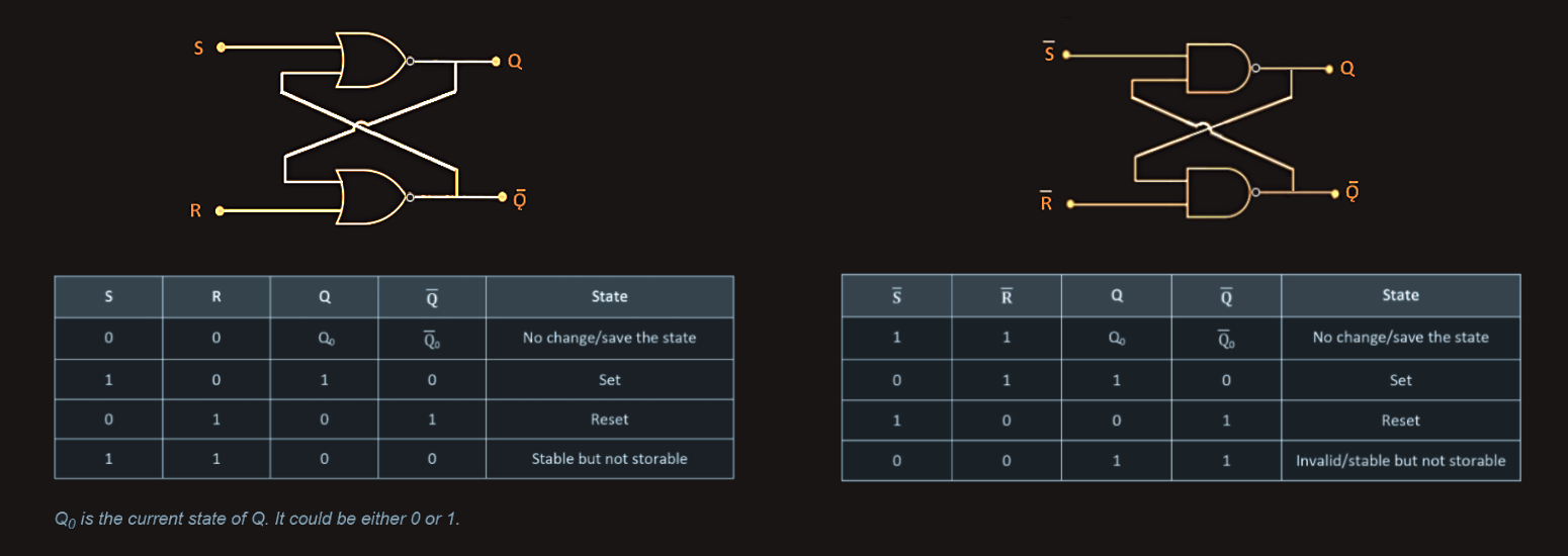
The RS flip-flop is a one-bit, bistable device and is considered to be one of the most basic sequential logic circuits.
It can be formed using NOR gates (‘active-high’ circuit) or using NAND gates (‘active-low’ circuit). The circuit takes feedback from both of its outputs back to its inputs so it effectively has four inputs: set, reset and the current states of Q and ‾Q‾. 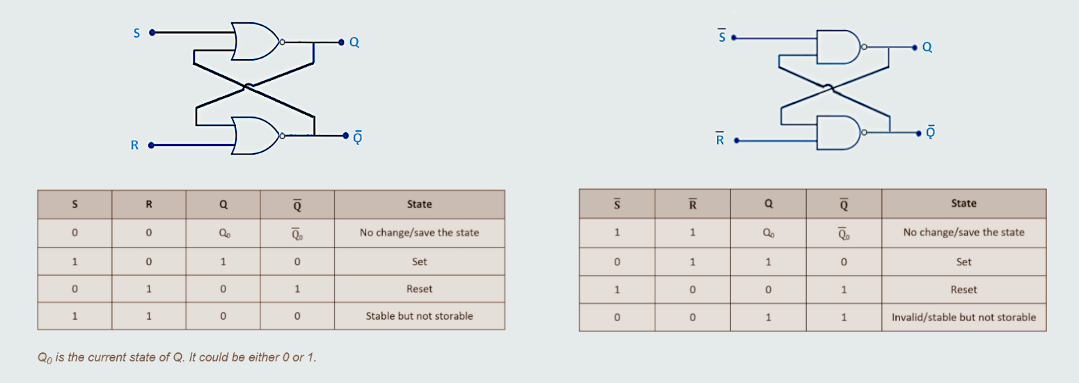
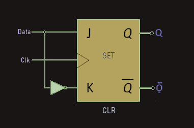
JK flip-flops
The JK flip-flop is named after Jack Kilby, the inventor of the circuit. It is the most widely used and is considered to be a universal flip-flop circuit. 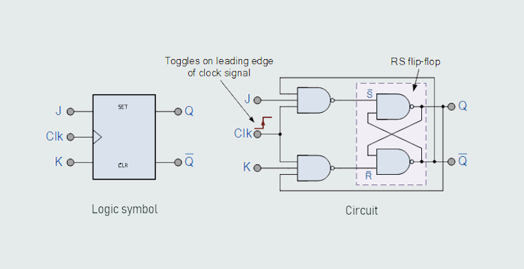
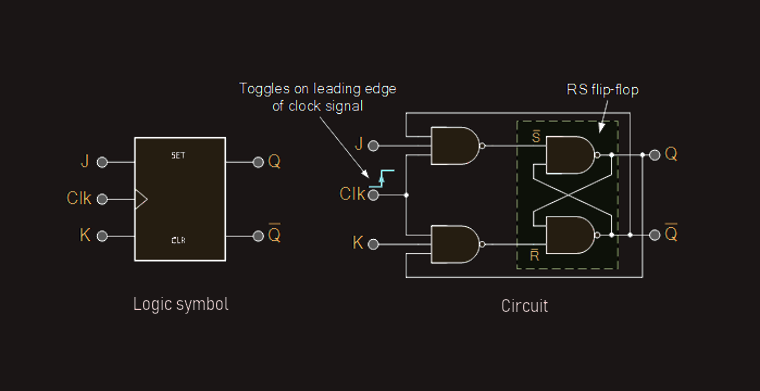 JK flip-flops look like RS flip-flops with an additional pair of three input NAND gates and feedback loops. The JK flip-flop overcomes the disadvantages of the RS flip-flop:
1. Its operation in the R = 1, S = 1 state is invalid, so that condition must be avoided.
2. It is transparent, which means whatever happens on the input side is directly transferred to the output side.
The output transitions are initiated by an additional clock input, so that it is not transparent and the 1,1 state causes the flip-flop to toggle, which means the outputs change from whichever state they are in to the other state.
D flip-flops
D flip-flops have one input, the D input, and data is transferred to the output at each clock pulse. So, it can be used as a delay. D flip-flop can be constructed using a JK flip-flop. It is a clocked flip-flop with a single digital input D. 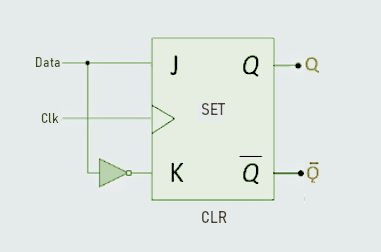
 Each time a D flip-flop is clocked, its output follows the state of D.
Counters
So, counters are used for counting. Counters are made using logic gates that can count the clock pulses in binary form. It is possible to make counters using RS, JK or D flip-flops and there are different design options; that we will not go further in details here. Synchronous counters are more complex in their design than asynchronous counters - all clock inputs of the flip-flops of a synchronous counter are driven from the input clock signal, which means all outputs change at the same time. This reduces the ripple effect, and there is no propagation delay.
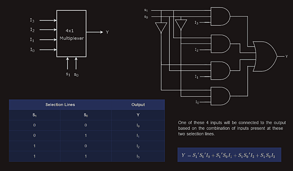
Multiplexers
A multiplexer is a circuit that is used in data communications. It can be thought of as a switch that has many inputs (D0, D1, D2 etc.) but only one output (Q), which is selected by a number of control lines (S0, S1 etc.). A particular output can be obtained by control of the registers that make the logic gates, allowing us to create permit lines.
So, multiplexer is a combinational circuit that has maximum of 2n data inputs, ‘n’ selection lines and single output line. One of these data inputs will be connected to the output based on the values of selection lines. Since there are ‘n’ selection lines, there will be 2n possible combinations of zeros and ones. So, each combination will select only one data input. Multiplexer is also called as MUX. 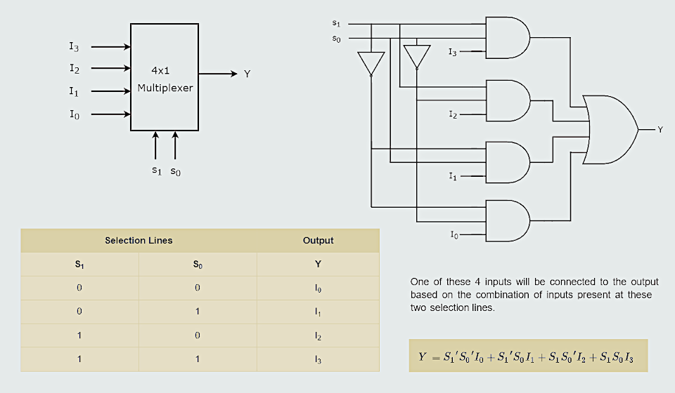
 Similarly, we can implement 8x1 MUX and 16x1 MUX by following the same procedure.
Let us implement 8x1 Multiplexer using 4x1 Multiplexers and 2x1 Multiplexer. We know that 4x1 Multiplexer has 4 data inputs, 2 selection lines and one output. Whereas, 8x1 Multiplexer has 8 data inputs, 3 selection lines and one output. So, we require two 4x1 Multiplexers in first stage in order to get the 8 data inputs. Since, each 4x1 Multiplexer produces one output, we require a 2x1 Multiplexer in second stage by considering the outputs of first stage as inputs and to produce the final output. 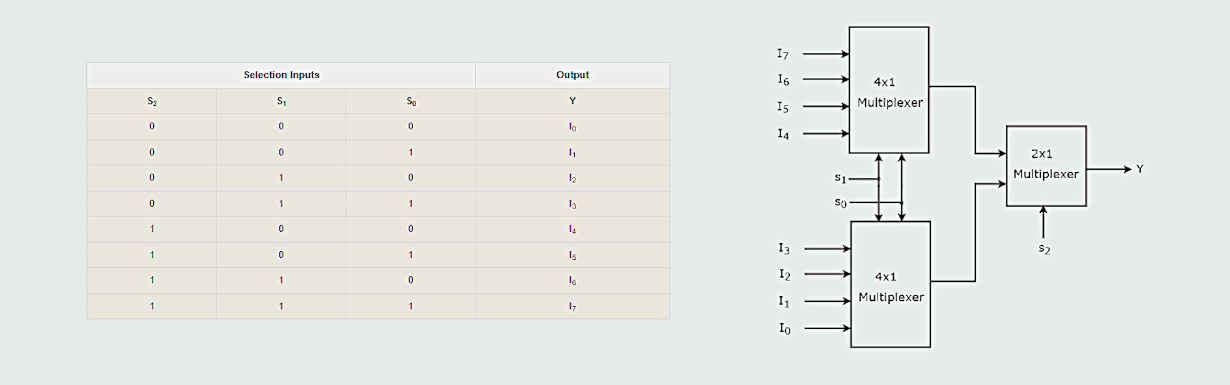
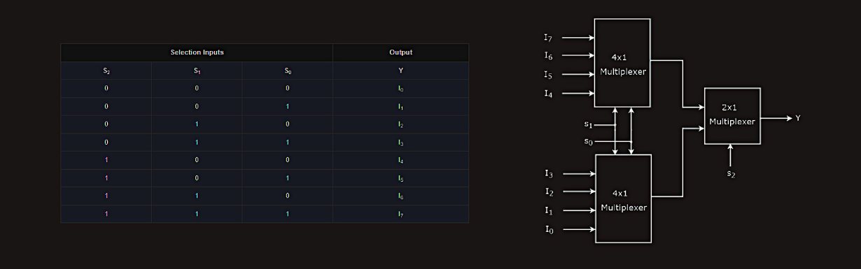 The same selection lines, s1 & s0 are applied to both 4x1 Multiplexers. The data inputs of upper 4x1 Multiplexer are I7 to I4 and the data inputs of lower 4x1 Multiplexer are I3 to I0. Therefore, each 4x1 Multiplexer produces an output based on the values of selection lines, s1 & s0. The outputs of first stage 4x1 Multiplexers are applied as inputs of 2x1 Multiplexer that is present in second stage. The other selection line, s2 is applied to 2x1 Multiplexer:
· If s2 is zero, then the output of 2x1 Multiplexer will be one of the 4 inputs I3 to I0 based on the values of selection lines s1 & s0.
· If s2 is one, then the output of 2x1 Multiplexer will be one of the 4 inputs I7 to I4 based on the values of selection lines s1 & s0.
Therefore, the overall combination of two 4x1 Multiplexers and one 2x1 Multiplexer performs as one 8x1 Multiplexer.