


Capacitors connected in parallel
Let us consider the general case of three different value capacitors connected in parallel to a d.c. supply of V volts.
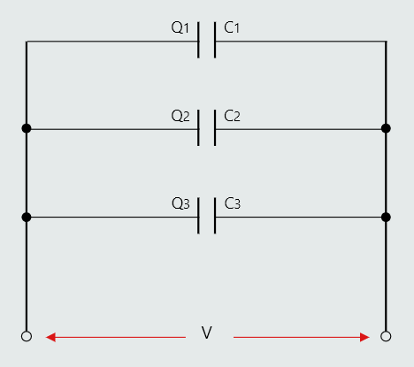
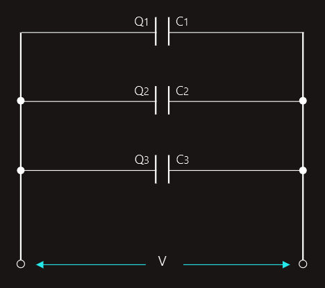
Each capacitor will take a charge from the supply according to its capacitance:
Q1=V‧C1
Q2=V‧C2
Q3=V‧C3
The total charge drawn from the supply must be: Q=Q1+Q2+Q3.
Also, we can express the total charge as Q=V‧C, where C is the total circuit capacitance.
Thus we have:
V‧C=V‧C1+V‧C2+V‧C3 and dividing through by V:
C=C1+C2+C3 .
Capacitors connected in series
Three parallel plate capacitors are shown connected in series. Each capacitor will receive a charge. However, we can ask ourselves how capacitor C2 can receive any charging current since it is 'sandwiched' between the other two, and of course the charging current cannot flow through the dielectrics of these. The answer lies in the explanation of the charging process described earlier. To assist the explanation, the plates of capacitors C1 to C3 have been labelled with letters.
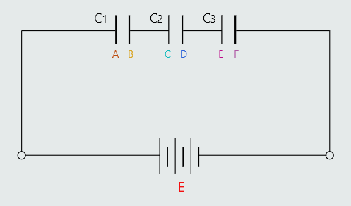
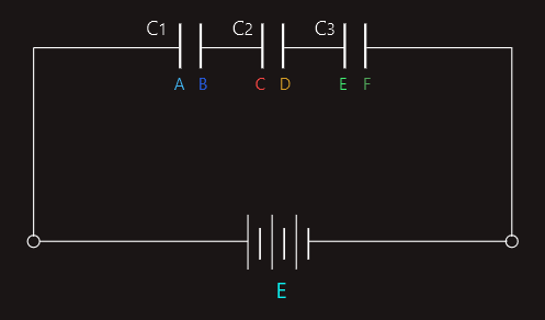
Plate A will lose electrons to the positive terminal of the supply, and so acquires a positive charge. This creates an electric field in the dielectric of C1 which will cause plate B to attract electrons from plate C of C2. The resulting electric field in C2 in turn causes plate D to attract electrons from plate E. Finally, plate F attracts electrons from the negative terminal of the supply. Thus all three capacitors become charged to the same value.
Since the capacitors are of different values then each will acquire a different p.d. between its plates.
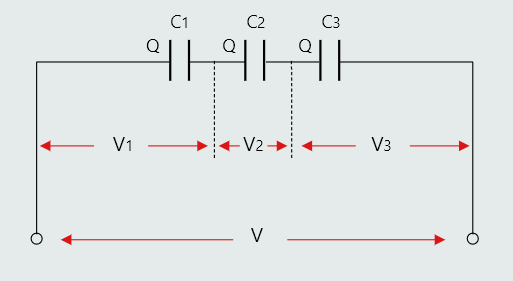
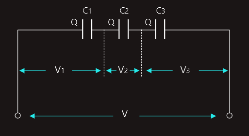
V1=Q/C1
V2=Q/C2
V3=Q/C3
We know that V=V1+V2+V3 and V=Q/C, where C is the total circuit capacitance.
Hence, Q/C=Q/C1+Q/C2+Q/C3 and dividing by Q:
1/C=1/C1+1/C2+1/C3 .
To obtain the value for C the reciprocal of the answer obtained from this equation must be found.
If only two capacitors are connected in series, then the total capacitance can be found directly by using 'product/sum' form, i.e. C=(C1‧C2)/(C1+C2)
Capacitors can also be connected in series-parallel, which is combination of these two explained, and for solving such a circuit we use the same method as for resistors, i.e. we are working step by step through the circuit until we get the solution.
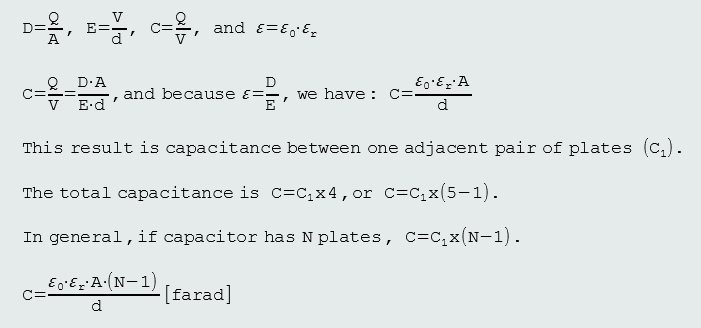
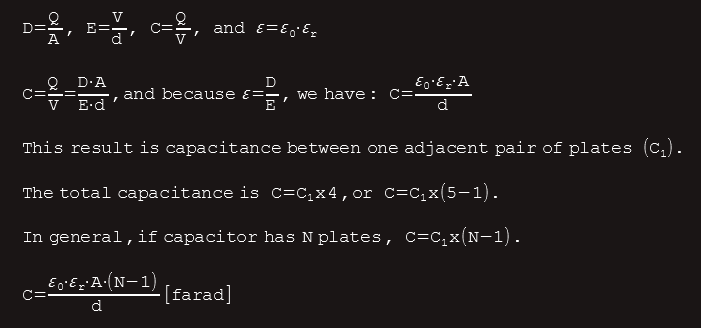
Multiplate capacitors
Most practical capacitors consist of more than one pair of parallel plates, and these are referred to as multiplate capacitors.
For example, one with a five plates is illustrated in the figure below.
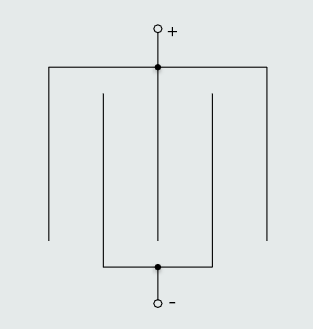
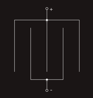
We can see that this capacitor effectively forms four identical capacitors, connected in parallel - because all the positive plates are joined together, and so too are the negative plates. The total capacitance of four identical capacitors connected in parallel is simply four times the capacitance of one of them.
Thus, this value will be the effective capacitance of the complete capacitor; so we have:
Energy stored
When a capacitor is connected to a voltage source of V volts it will charge up until the p.d. between the plates is also V volts. If the capacitor is now disconnected from the supply, the charge and p.d. between its plates will be retained.
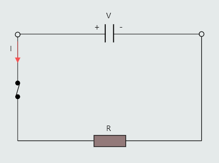
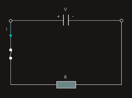
If the resistor is connected with the capacitor, as shown in the figure, the capacitor will act as if it were a source of emf.
It will therefore drive current through the resistor, so capacitor is becoming discharged. This discharge process will continue until the capacitor becomes completely discharged, when both plates become electrically neutral. Discharge current marked on the diagram indicates conventional current flow.
However, if a discharge current flows then work must be done (energy is being dissipated). The only possible source of this energy in these circumstances must be the capacitor itself. Thus the charged capacitor must store energy.
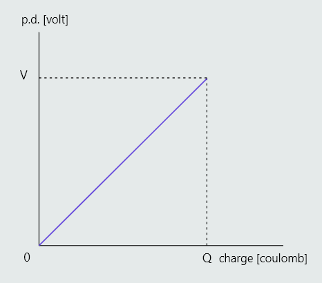
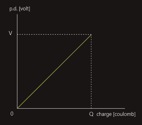
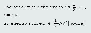
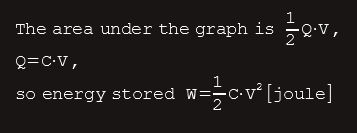
If a graph is plotted of capacitor p.d. to the charge it receives, the area under the graph represents the energy stored. Assuming a constant charging current, the graph will be:
There is a maximum potential gradient that any insulating material can withstand before dielectric breakdown occurs. Capacitors normally have marked on them a maximum working voltage. When in use we must ensure that the voltage applied between its terminals does not exceed this value, otherwise dielectric breakdown will occur. Dielectric breakdown is the effect produced in an insulating material when the voltage applied across it is more than it can withstand. The result is that the material is forced to conduct. However when this happens, the sudden surge of current through it will cause it to burn, melt, vaporise or be permanently damaged in some other way.
Example:
A capacitor is designed to be operated from a 400 V supply, and uses a dielectric which (allowing for a factor of safety), has a dielectric strength of 0.5 MV/m. Calculate the minimum thickness of dielectric required.
Solution:
V=400V
E=0,5x10⁶V/m
-------------------------------
E=V/d
d=V/E
d=400/(500000) -> d=0,0008m
d=0,8mm
The main difference between capacitor types is in the dielectric used. There are a number of factors that will influence the choice of capacitor type for a given application. Amongst these are the capacitance value, the working voltage, the tolerance, the stability, the leakage resistance, the size and the price.