


Filters
A filter is a circuit capable of passing (or amplifying) certain frequencies while attenuating other frequencies. Thus, a filter can extract important frequencies from signals that also contain undesirable or irrelevant frequencies. In many practical applications of complex circuits, various combinations of direct, low-frequency, audio-frequency, and radio-frequency currents may exist. It is frequently necessary to have a means for separating these component currents at any desired point. An electrical device for accomplishing this separation is called a filter. A filter circuit consists of inductance, capacitance, and resistance used singularly or in combination, depending upon the purpose. The use of resistance by itself in filter circuits does not provide any filtering action, because it opposes the flow of any current regardless of its frequency. What it does, when connected in series or parallel with an inductor or capacitor, is to decrease the "sharpness", or selectivity, of the filter. Hence, in some particular application, resistance might be used in conjunction with inductance or capacitance to provide filtering action over a wider band of frequencies. Filter circuits may be divided into four general types: low-pass, high-pass, band-pass, and band-reject filters.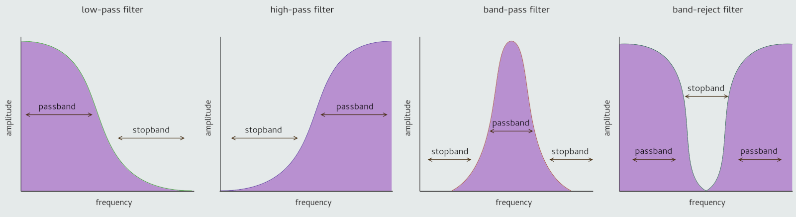
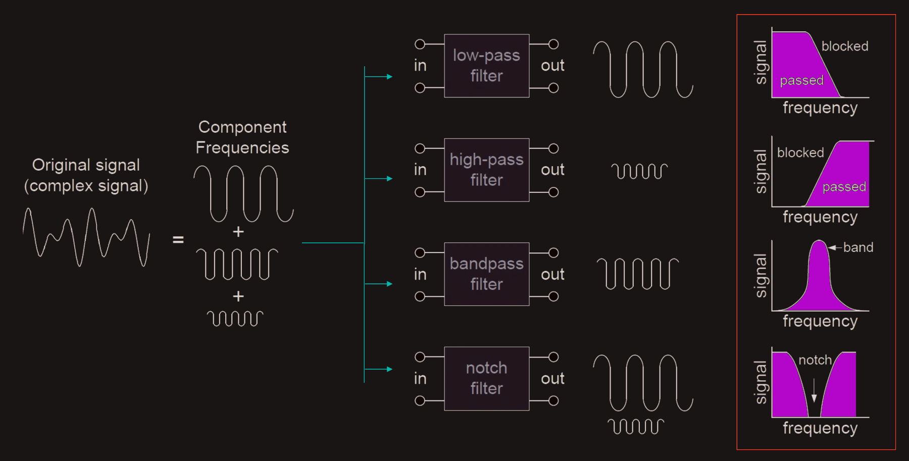
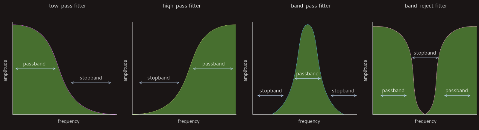 Band-pass and band-reject filters are basically combinations of low-pass and high-pass filters. A band-pass filter lets through only frequencies above a certain point and below another, so there is a band of frequencies that get through. A band-reject filter is the opposite: it stops a band of frequencies. Band-reject filters are sometimes called notch filters, also.
Filters serve a critical role in many common applications. Such applications include power supplies, audio electronics, and radio communications. Filters can be active or passive, and the four main types of filters are low-pass, high-pass, band-pass, and notch/band-reject. Passive filters include only passive components — resistors, capacitors, and inductors. In contrast, active filters use active components, such as op-amps (operational amplifiers), in addition to resistors and capacitors, but not inductors.
Response curves are used to describe how a filter behaves. A response curve is simply a graph showing an attenuation ratio (VOUT / VIN) versus frequency, shown above.
The applications of high pass and low pass filters extend beyond audio engineering and production. In telecommunications, high pass and low pass filters are utilized for signal processing and frequency modulation. High pass filters are used to allow only high-frequency signals to pass through, while low pass filters permit only low-frequency signals, enabling the segregation and manipulation of specific frequency ranges. In electronic devices, these filters are employed to control the flow of current and voltage, ensuring that only the desired frequencies are transmitted or received. The versatility of high pass and low pass filters makes them indispensable in a wide range of technical applications.
The difference between a low pass filter and a high pass filter is that a low pass filter will allow signals lower than a cut-off frequency to pass, while a high pass filter will allow signals higher than a cut-off frequency to pass.
It’s important to recognize that filters don’t create signals or change one frequency to another. For instance, a high-pass filter can’t create the high frequencies that they output. Instead, the input waveform contains a combination of high and low frequencies, and the high-pass filter prevents the low frequencies from passing through it. 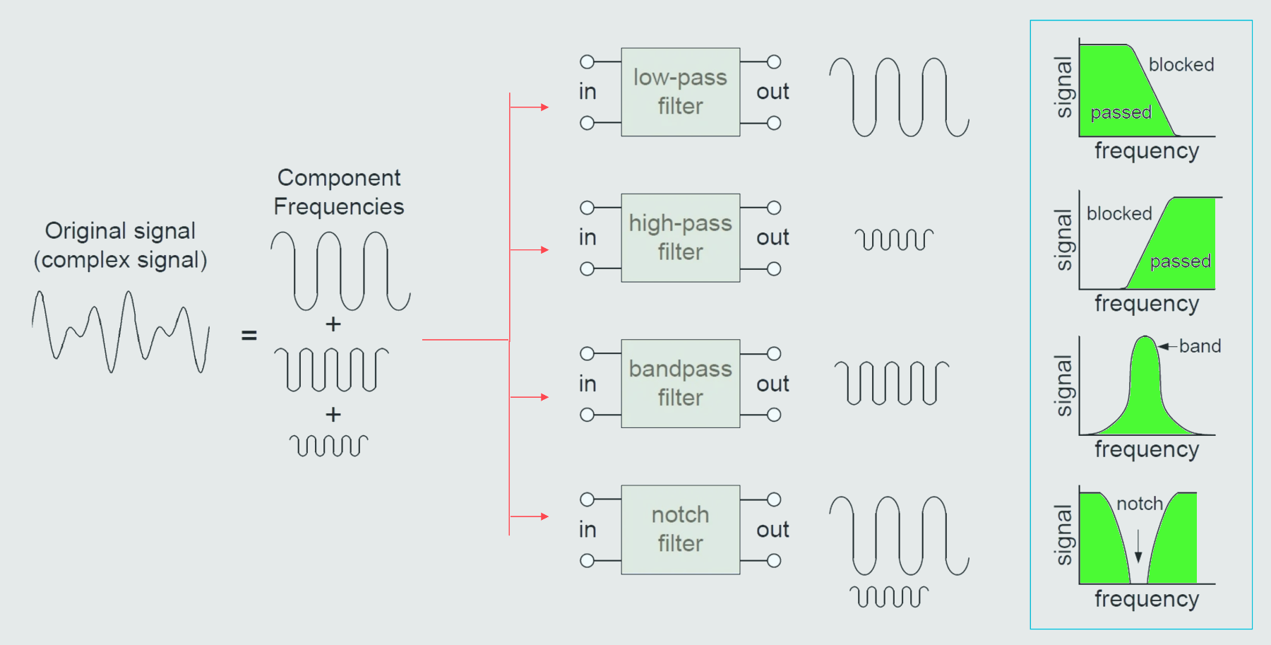
High pass filters operate by allowing frequencies above the cutoff point to pass through while attenuating frequencies below that point. This is achieved through the use of capacitors, inductors, or a combination of both. When a signal passes through a high pass filter, frequencies below the cutoff point encounter resistance, causing them to be attenuated or blocked. Meanwhile, frequencies above the cutoff point experience minimal resistance and are allowed to pass through relatively unaffected.
In contrast to high pass filters, low pass filters allow frequencies below the cutoff point to pass through while attenuating frequencies above that point. This is achieved through the use of capacitors, inductors, or a combination of both, which create a path for low-frequency signals to pass through while impeding the passage of high-frequency signals.
The process of removing unwanted frequencies is called attenuation. A low pass filter primarily attenuates high frequencies, while a high pass filter primarily attenuates low frequencies.
Filters are designed with a specific frequency in mind which is called the cut-off frequency.
Low pass filters are designed to pass frequencies below the cut-off frequency. A perfect low pass filter would pass all frequencies below the cut-off frequency, and none of the frequencies above the cut-off frequency.
High pass filters are designed to pass frequencies above the cut-off frequency. A perfect high pass filter would pass all frequencies above the cut-off frequency, and none of the frequencies below the cut-off frequency.
Since capacitive reactance depends on the signal frequency, filters can be designed so that the reactance dramatically increases either above or below the cut-off frequency. A low-pass filter will be designed so that the reactance increases above the cut-off frequency, with little to no reactance below the cut-off frequency. A high pass filter will be designed so that reactance increases below the cut-off frequency, with little to no reactance above the cut-off frequency.
Both high and low pass filters use a combination of resistor and capacitor, but the arrangement is reversed in each, so that the desired output can be obtained. 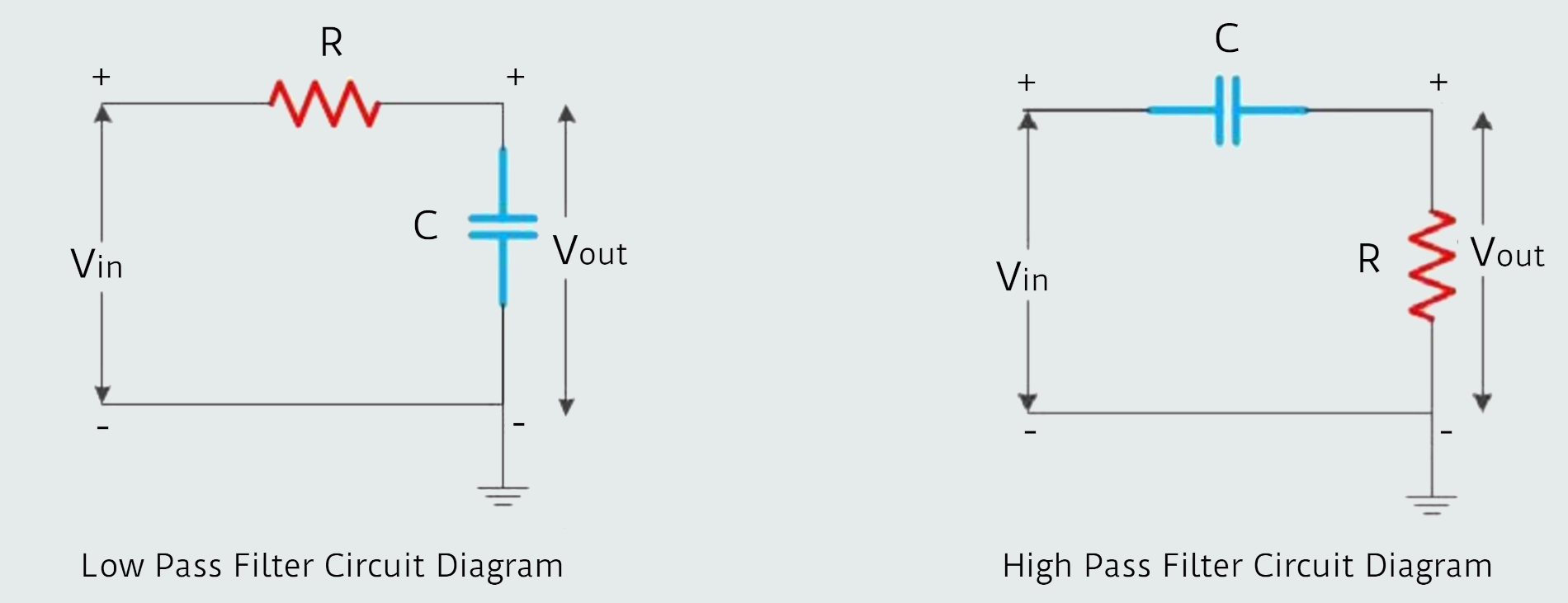
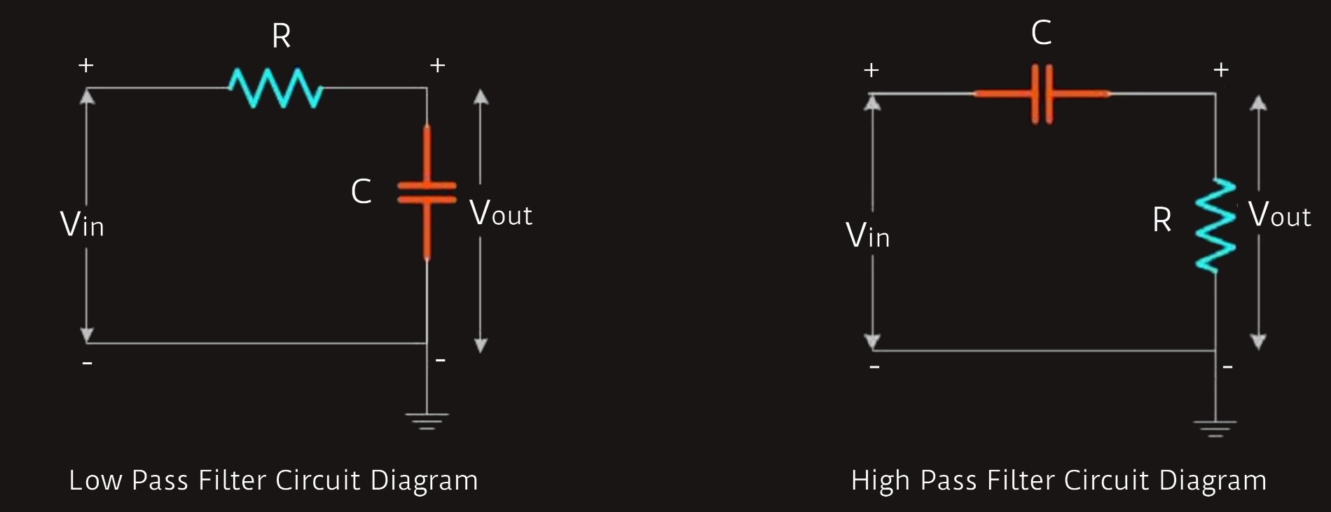 A low pass filter has the input signal applied directly to the resistor, and the output is measured across the capacitor. A high pass filter has the input signal applied directly to the capacitor, and the output is measured across the resistor.
The characteristics of both the low pass filter and the high pass filter comes from the interplay of capacitive reactance and resistance, which both contribute to the total impedance.
The impedance contributed by the resistor (i.e. resistance) doesn’t depend on the frequency, but the capacitive reactance is inversely proportional to the frequency. This means that at low frequencies, the capacitive reactance is high while at high frequencies, the capacitive reactance is low.
XC=1/(2π·fc·C)
fc - cut-off frequency
fhpf ≥ fc /hpf - high pass filter
A simple way to think about low pass filters is with regards to the capacitive reactance and its effect on the voltage drop across the capacitor, which is the output voltage. At high frequencies, the capacitive reactance is low. This means that the capacitor allows the signal to pass to ground without generating a significant voltage drop across it. So, in this condition, the output voltage obtained is zero as the entire voltage is passed to ground. At low frequencies, however, the resistance will offer the same obstruction as in the case of high-frequency signal, but the capacitive reactance is high, and the capacitor has a significant voltage drop across it. So, the signal cannot pass through the capacitor path. A higher voltage drop means a high output voltage for the circuit. Thus he entire low-frequency signal is passed to the output terminal.
A simple way to think about high pass filters is with regards to the capacitive reactance and its effect on the voltage drop across the resistor. At low frequencies, the capacitive reactance is high, and the capacitor has a significant voltage drop across it. The bulk of the voltage drop thus occurs across the capacitor, leaving little voltage to drop across the resistor. At high frequencies, the capacitive reactance is low. The majority of the voltage must therefore be dropped by the resistor, leading to a high output voltage at high frequencies.