


Combinational circuits
Combinational logic is used to build circuits that contain basic Boolean operators, inputs, and outputs. The key concept in recognizing a combinational circuit is that an output is always based entirely on the given inputs. Thus, the output of a combinational circuit is a function of its inputs, and the output is uniquely determined by the values of the inputs at any given moment. A given combinational circuit may have several outputs. If so, each output represents a different Boolean function.
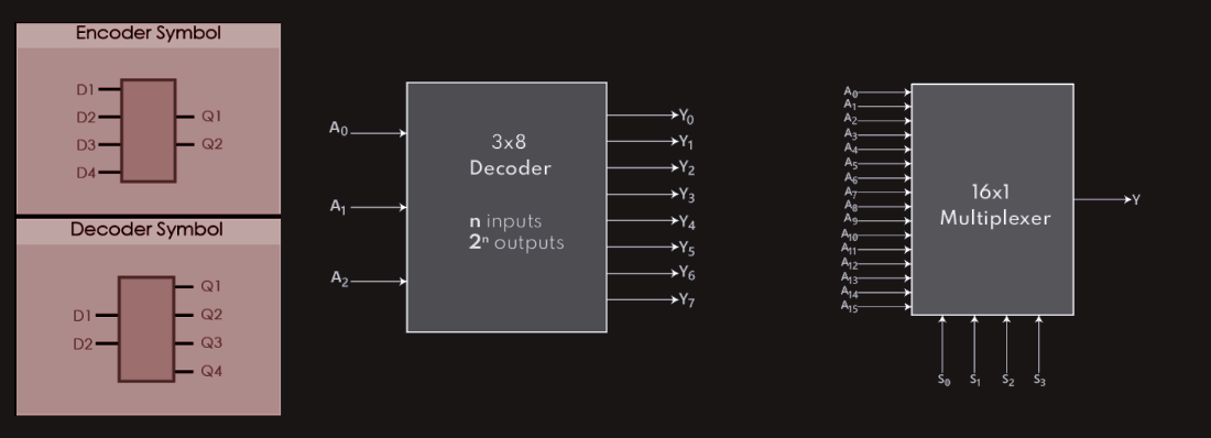
Examples of combinational circuits are: Half-Adder, Full Adder, Decoder, Multiplexer etc. 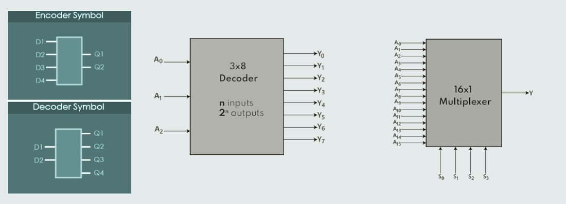
Sequential circuits
The major weakness of combinational circuits is that there is no concept of storage. We know that computers must have a way to remember values. A sequential circuit defines its output as a function of both its current inputs and its previous inputs. Therefore, the output depends on past inputs. To remember previous inputs, sequential circuits must have some sort of storage element. This storage element is typically refered to as a flip-flop. The state of this flip-flop is a function of the previous inputs to the circuit. Therefore, pending output depends on both the current inputs and the current state of the circuit.
Clocks
Before we discuss sequential logic, we should understand the fact that a sequential circuit uses past inputs to determine present outputs which indicates that we must have event ordering. Some sequential circuits are asynchronous, which means they become active the moment any input value changes. Synchronous sequential circuits use clocks to order events.
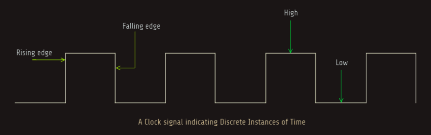
A clock is a circuit that emits a series of pulses with a precise pulse width and a precise interval between consecutive pulses. This interval is called the clock cycle time. Clock speed is generally measured in megahertz (MHz) or gigahertz (GHz). A clock is used by a sequential circuit to decide when to update the state of the circuit (when do “present” inputs become “past” inputs). This means that inputs to the circuit can only affect the storage element at given, discrete instances of time.
Most sequential circuits are edge triggered (as opposed to being level triggered). This means they are allowed to change their states on either the rising or falling edge of the clock signal. 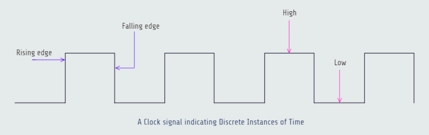
Flip-Flops
A level-triggered circuit is allowed to change state whenever the clock signal is either high or low. Technically, a latch is level triggered, whereas a flip-flop is edge triggered. William Eccles and F. W. Jordan invented the first flip-flop (from vacuum tubes) in 1918. Like so many other inventions, they were originally named after the inventors and were called Eccles–Jordan trigger circuits. The term "flip-flop" came from the sound the circuit made when it was triggered; others believe it came from the circuit’s ability to flip from one state to another and back again. To “remember” a past state, sequential circuits rely on a concept called feedback. This simply means the output of a circuit is fed back as an input to the same circuit. One very simple feedback circuit uses two NOT gates. 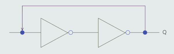
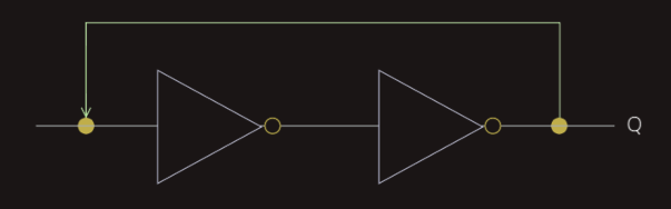 In this figure, if Q is 0, it will always be 0. If Q is 1, it will always be 1.
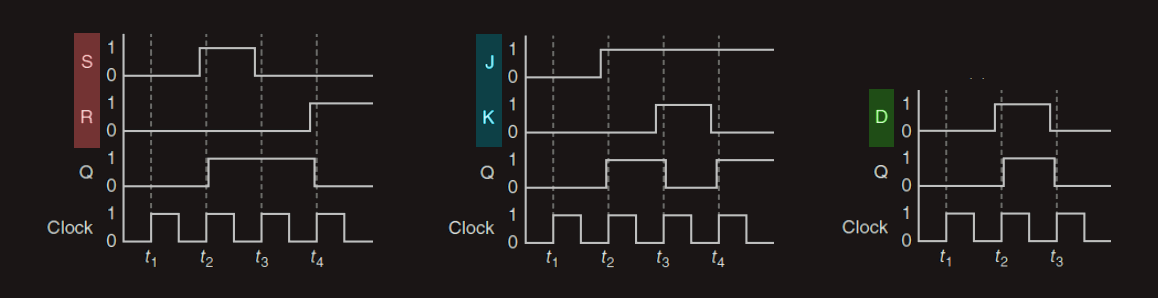
We have introduced earlier SR flip-flop, JK flip-flop and D flip-flop.
SR stands for set/reset.
Here we will only show timing diagrams for these flip-flops without going deeper into analysis... 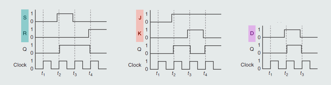
 Some believe JK flip-flop was named after Jack Kilby, inventor of the integrated circuit. Others believe it is named after John Kardash, who is often credited as its inventor, still others believe it was coined by workers at Hughes Aircraft who labeled circuits input using letters, and J and K just happened to be next on the list.
Another variant of the SR flip-flop is the D (data) flip-flop. A D flip-flop is a true representation of physical computer memory. This sequential circuit stores one bit of information. If a 1 is asserted on the input line D, and the clock is pulsed, the output line Q becomes a 1. If a 0 is asserted on the input line and the clock is pulsed, the output becomes 0. Since output Q represents the current state of the circuit, an output value of 1 means the circuit is currently “storing” a value of 1.
Microchips – also referred to as integrated circuits – are considered to be among the greatest technological achievements of the last century. The range of devices that rely on microchips still increases at an amazing rate and includes desktop and laptop computers, servers, tablets, smartphones, smartwatches, flash drives, portable music players, game consoles, cameras, televisions, electronic household appliances, elevators, cars and traffic guidance systems, airplanes, and countless others. They are fascinating pieces of technology that consist of millions or often billions of microscopic transistors. Just as fascinating as transistor counts is the speed that modern integrated circuits operate, which can even be in the range of 4 gigahertz (4 billion operations per second).
Microchips do not all work the same. In fact, there are thousands of different chips for today's large variety of technical devices. Only just a few types of ICs are standardized so they can be bought by consumers to upgrade, for example, their personal computer. However, the majority of ICs produced are highly customized for use in very specialized equipment like industrial machinery, aircraft control systems, medical devices, remote controls, etc.
At around 1940, computers consisted of thousands of vacuum tubes that were individually wired together in a very complex and expensive way. This design not only required a great deal of electricity, but it was also very maintenance-intensive. The ENIAC computer from 1946 had over 17.000 vacuum tubes and suffered a tube failure on average every two days, which was time-consuming to troubleshoot and repair. With the invention of the transistor in 1947 by Bell Labs, the components became significantly smaller, but the transistors were still wired together individually. This reduced power consumption of those computers and their overall size, but not their wiring complexity. It was not before the invention of integrated circuits before computers became way more efficient and easier to operate and maintain.
The large success of integrated circuits can be attributed to several different factors and advantages:
· Low size and weight
· Low power consumption
· Increased operating speed
· Low production cost
· High overall reliability
· High temperature stability
· Low maintenance cost
Manufacturing a modern integrated circuit, from sand to silicon, can take over 400 steps in the process, as layers of material are deposited and removed over and over again to create desired patterns. In addition, numerous very complex production technologies involving atomic diffusion, metallization, etching, exposure to ions and special light, and others are required to develop structures on a substrate. Once the manufacturing process has started, even a single dust particle can ruin an entire microchip. For that reason, integrated circuits are fabricated in special clean rooms. These offer a dust-free environment with stable temperature and humidity levels.
Microchips come in various shapes and with various sizes. What they all have in common is that their outer appearance doesn’t reveal what’s inside.
The complexity within an integrated circuit that has millions or even billions of transistors is incredibly high. It is therefore impossible to look onto an IC chip through a microscope and to comprehend the range of functions the particular chip offers. The only conceivable way to understand integrated circuits is to focus on individual levels of abstraction and to understand the underlying electronic principles of that level before looking at another level.
· Transistor Level: This level of abstraction focuses on transistors, the smallest devices within an integrated circuit.
· Circuit Level: Technically not a separate level of abstraction, but helps to understand how transistors operate.
· Logic Gates Level: Circuit designs to create logic gates (AND, OR, NOT and others).
· Register Transfer Level: Combination of logic gates to create functional units (latches, flip flops, registers, encoders, decoders, multiplexers, demultiplexers, arithmetic logic units).
· Microarchitecture Level: Also known as Architecture level. Interactions and data flows between functional units, control units.
· System Level: Design of what the chip is and how it behaves (central processing unit, graphics processing unit, memory, system-on-a-chip, others), definition of input and output.