


Three-phase, four-wire system
Three-phase alternator actually represents three identical single-phase alternators contained in the one machine. The three stator windings are brought out to their own separate pairs of terminals on the stator casing. These stator windings are referred to as phase windings, or phases. They are identified by the colours red, yellow and blue.
In the figure below the three phase windings are shown connected, each one to its own separate load. This arrangement is known as a three-phase, six-wire system. However, three-phase alternators are rarely connected in this way. 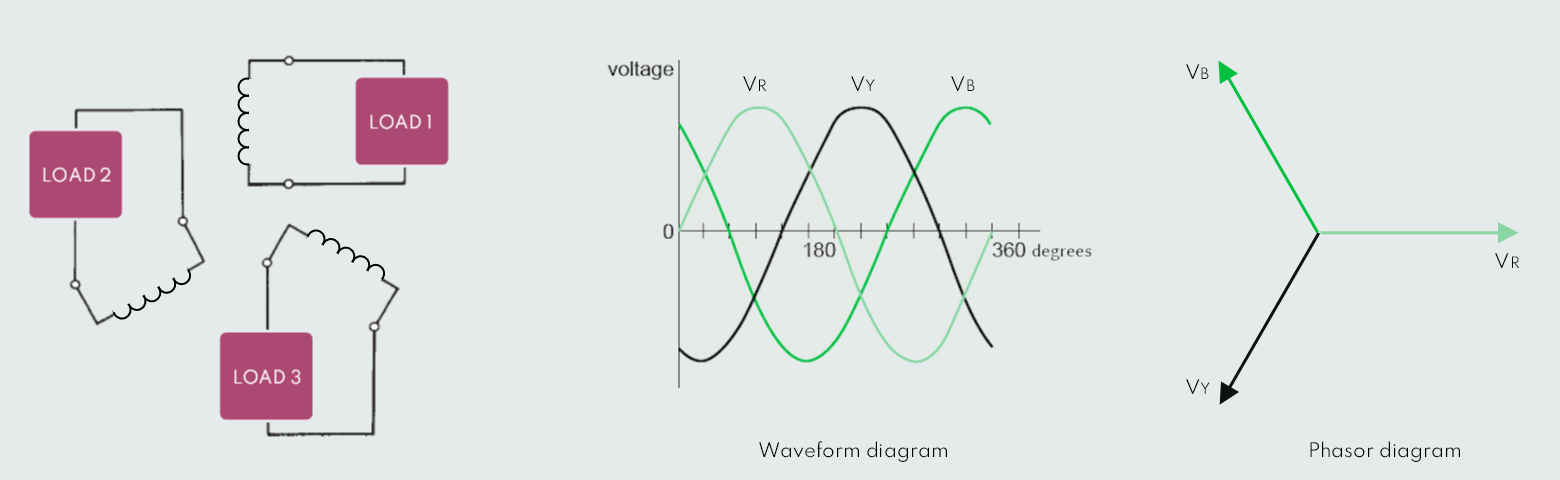
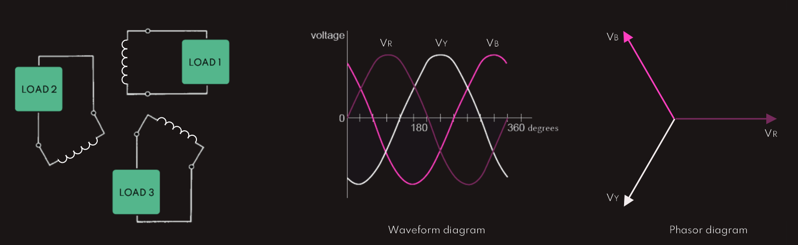
By convention, the reference is always taken to be the red phase voltage. The yellow phase lags the red by 120°, and the blue lags the red by 240° (leads the red by 120°). The windings are arranged so that when the rotor is driven in the chosen direction, the phase sequence is red, yellow, blue.
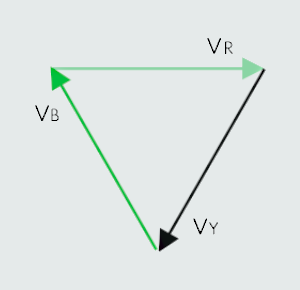
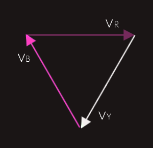
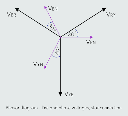
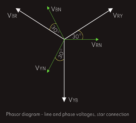
It may be seen from the waveform diagram that at any point along the horizontal axis, the sum of the three voltages is zero. This fact becomes even more apparent if the phasor diagram is redrawn, like shown here:
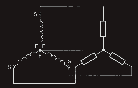
It is not necessary, though, to have six wires from the three phase windings to the three loads, provided there is a common ‘return’ line. Each winding will have a ‘start’ (S) and a ‘finish’ (F) end. The common connection mentioned above is achieved by connecting the corresponding ends of the three phases together. For example, either the three ‘F’ ends or the three ‘S’ ends are commoned. This form of connection is shown below and is known as a star or Y connection. With the resulting 4-wire system, the three loads also are connected in star configuration. The three outer wires are called the lines, and the common wire in the centre is called the neutral. 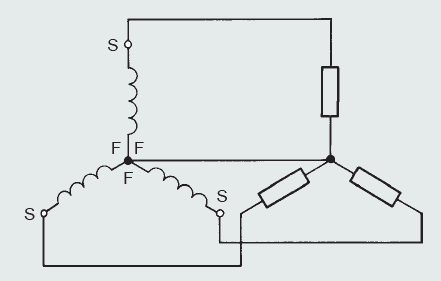
 If the three loads were identical in every way (same impedance and phase angle), then the currents flowing in the three lines would be identical. These three currents meet at the star point of the load. The resultant current returning down the neutral wire would therefore be zero. The load in this case is known as a balanced load, and the neutral is not strictly necessary, but it is difficult, in practice, to ensure that each of the three loads are exactly balanced. For this reason the neutral is left in place. Also, since it has to carry only the relatively small ‘out-of-balance’ current, it is made half the cross-sectional area of the lines.
Let us now suppose that three identical loads are to be supplied with 200 A each. The two lines from a single-phase alternator would have to carry the total 600 A required. If a 3-phase, 6-wire system was used, then each line would have to carry only 200 A. Thus, the conductor csa would only need to be 1/3 that for the single-phase system, but of course, being six lines would entail using the same total amount of conductor material. If a 4-wire, 3-phase system is used, there will be a saving on conductor costs in the ratio of 3.5:6 (0.5 being due to the neutral). If the power has to be sent over long transmission lines, then the 3-phase, 4-wire system yields an enormous saving in cable costs, which is one of the reasons why the power generating companies use three-phase, star-connected generators to supply the grid system.
Next figure represents the stator of a 3-phase alternator connected to a 3-phase balanced load. 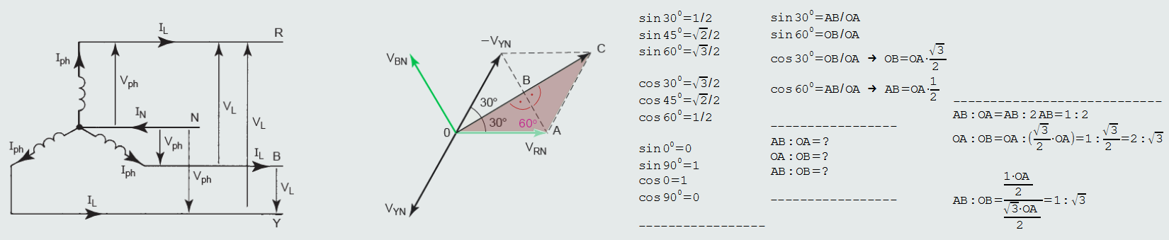
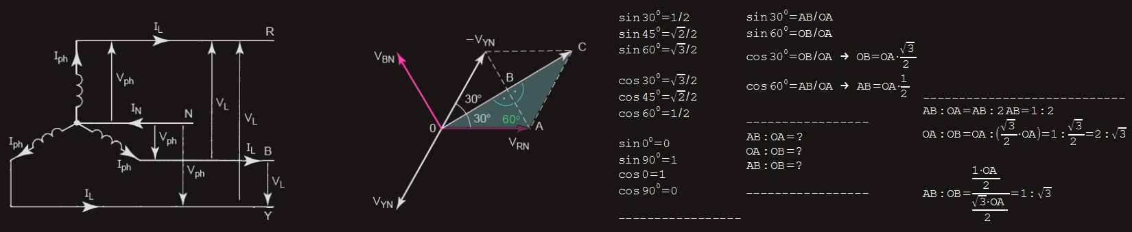 A line voltage is the phasor difference between the appropriate pair of phase voltages, that we can get using parallelogram method. This parallelogram consists of two isosceles triangles, such as OCA. Another property of a parallelogram is that its diagonals bisect each other at right angles. Thus, triangle OCA consists of two equal right-angled triangles, OAB and ABC.
Since triangle OAB is a 30°, 60°, 90° triangle, then the ratios of its sides AB:OA:OB will be 1:2:√3, respectively.
OB:OA = √3:2
OB = (√3:2) x OA
OC = 2 x OB = √3 x OA
OC = VRY & OA = VRN
VRY = √3 VRN
Using the same technique, we can get another two formulas:
VYB = √3 VYN and VBR = √3 VBN
So, finally, in star configuration: VLine = √3 VPhase
ILine = IPhase
Another advantage of a 3-phase system compared with single-phase is that the star-connected system provides two alternative voltage outputs from a single machine. For this reason, the stators of all alternators used in electricity power stations are connected in star configuration.
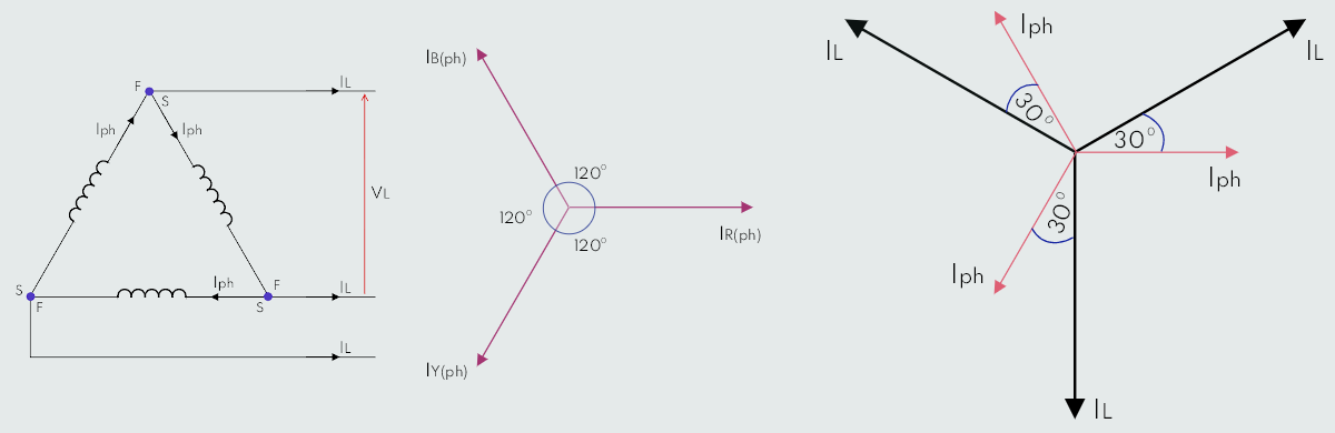
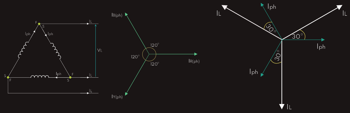
Above we have delta connection; it is apparent that each pair of lines is connected across a phase winding, so VLine = VPhase. Current along each line is the phasor difference of a pair of phase currents. The three phase currents are mutually displaced by 120°; using exactly the same geometrical technique as that for the phase and line voltages in the star connection, it can be shown that ILine = √3 IPhase.
We can see that the provision of a neutral wire is not applicable with a delta connection, but provided that the load is balanced, there is no requirement for one. If the load is unbalanced, then equalities of the three phase currents and the three line currents do not exist, and each phase or line current would have to be calculated separately.