


We have learned that whenever a current drifts through a conductor, a magnetic field surrounds that current. Accordingly, if currents move through each of two, parallel conductors, then the resulting magnetic fields will react with each other, and produce a force between the two conductors. This force may be one of attraction or of repulsion, depending upon the relative directions of the electric currents in the conductors.
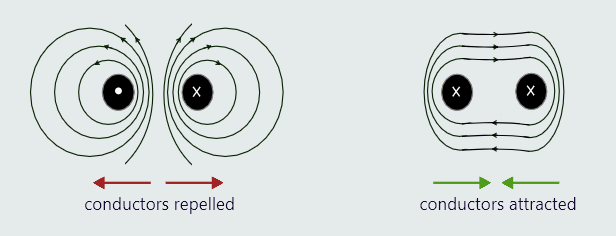
We can see that if the currents are drifting in opposite directions, the resulting force between them will be one of repulsion; whereas if the currents are drifting in the same direction, then the resulting force will be one of attraction.
The forces between magnetic fields are very important in electrical engineering because, let us say here, that the operation of electric motors is entirely dependent upon these forces.
Let us consider now the case when a current-carrying conductor is placed within a permanent magnetic field shown on the next figure. Again, the two fields will react with each other, causing a force to act upon the conductor.
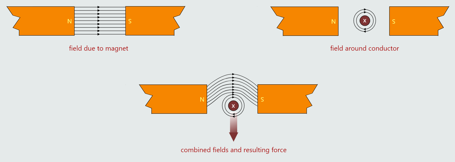
Since lines of magnetic flux never cross, they will either act to reinforce each other whenever they act in the same direction or, when they act in opposite directions, they will act to weaken each other. In the case shown, the resulting force will attempt to push the conductor out of the permanent field.
The force, which acts to push the conductor out of the magnetic field, is known as the ‘Lorentz Force’, in honour of the Dutch physicist, Hendrik Antoon Lorentz (1853–1928). This behaviour is known as motor action, because it is the basis of how electric motors work. The above principle is also used to extinguish electric arcs in certain types of circuit breaker.
The magnitude of the resulting force on the conductor depends upon the flux density of the permanent magnetic field, the current in the conductor, and the length of conductor within the field:


- F - force (N)
- B - flux density (T)
- I - current through a conductor (A)
- l - length of conductor in field (m)
The direction of the force on a conductor may be determined by using Fleming’s Left-Hand Rule for conventional current. This rule was created by the British engineer and academic, Sir John Ambrose Fleming (1849–1945). Fleming, in fact, devised two such rules. His ‘Left-Hand Rule’ (for conventional flow) applies to motors, whereas his ‘Right-Hand Rule’ (for conventional flow) applies to generators.
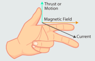
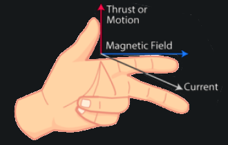
- • the first finger indicates the direction of the permanent field
- • the second finger indicates the direction of the current
- • the thumb will then indicate the direction of the resulting motion
Physical Equivalents of Electrical Components
As we have learned, voltage is the potential of the charges in the circuit, current is the amount of charge flowing in the circuit. Voltage, current, and power in electrical terms are related in a simple relationship: voltage * current = power.
So, to get power, we need both voltage and current. If either one of these is zero, we get zero power output.
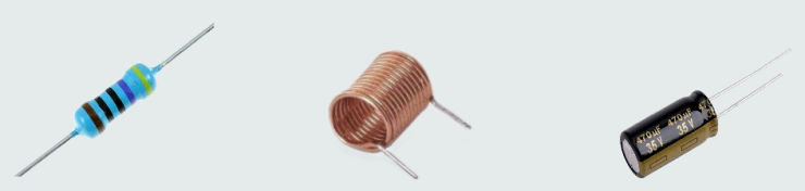
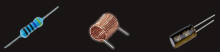
There are three fundamental components in virtually every circuit: resistor, inductor, and capacitor, and we will now see how they interact with electrical charges to gain insight about what is happening in an electronic circuit.
Any component used in a circuit has a tolerance. The tolerance of a component is a measure of accuracy and indicates how much the measured actual value is different from its nominal expected value. For instance, a resistor with nominal value of 1 kΩ and tolerance of 5% may have any value between 1 kΩ × 0.95 = 0.95 kΩ and 1 kΩ × 1.05 = 1.05 kΩ.
The Resistor Is Analogous to Friction
When we drag a heavy box across the floor, as shown in figure below, a force called friction resists the movement of the box. This friction is related to the speed of the box. It can be described by an equation: friction = force/speed .
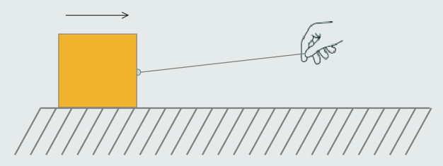
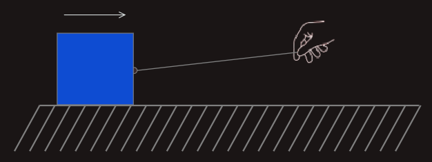
Furthermore, the friction dissipates the energy loss in the system with heat. For example, by rubbing our hands together, we would feel the heat. That is caused by friction.
The function of a resistor in an electrical circuit is equal to friction.
The resistor resists the flow of electricity, just like friction resists the speed of the box. And also, it heats up as it does so. This relationship is described by Ohm's law: resistance = voltage/current .
This relation is similar to friction relation, only real difference is in units working with.
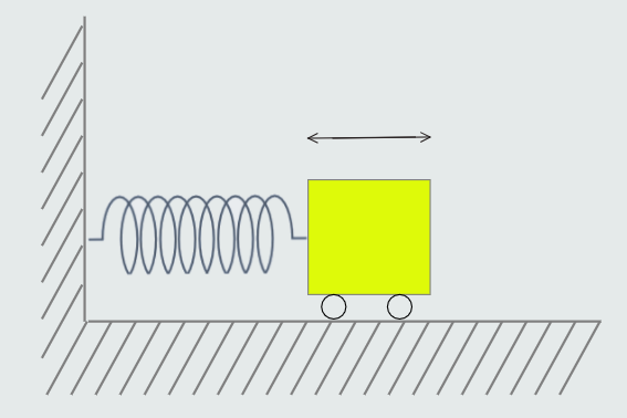
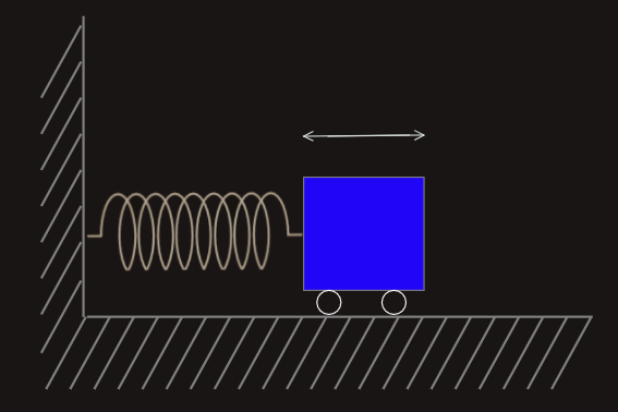
The Inductor Is Analogous to Mass
Let us stay on the box example and we will consider now the box with eliminated friction. Actually, we have a box on a frictionless wheels on a smooth track, shown below.
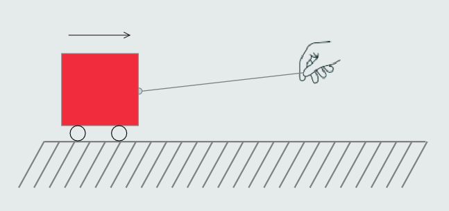
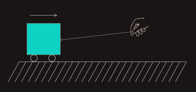
We would notice that it takes some work to get the box going, but once it’s moving, it goes along nicely. In fact, it takes work to get it to stop again. How much work it takes depends on how heavy the box is. This is known as the law of inertia, the idea postulated by Newton long before electricity was discovered, but it applies very well to inductance.
Mass impedes a change in speed. Correspondingly, inductance impedes a change in current.
mass = (force*time)/speed
inductance = (voltage*time)/current
The Capacitor Is Analogous to a Spring
We are now going to consider spring example. When we stretch it out and hold it, and then let it go, what happens? It snaps back into position, as shown below.
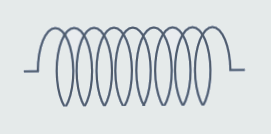
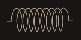
A spring has the capacity to store energy. When a force is applied, it will hold that energy until it is released. Capacitance is similar to the elasticity of the spring (the spring constant is the inverse of the elasticity).
spring = (speed*time)/force
capacitance = (current*time)/voltage
A Complex Circuit
Let's think about an inductor and a capacitor, a mass and spring. In a thought experiment, we will hook the spring up to the box from the previous drawing and give it a tug. What happens? It oscillates — bounces back and forth. A perfect circuit would go on forever at the resonant frequency.
Here we actually have LC circuit, and if we follow this reasoning to RLC circuit, all we need to do is add a little resistance, or friction, to the mass-spring of the circuit.
Let’s tighten the wheels on our box a little too much so that they rub.
What will happen after we give the box a tug? It will bounce back and forth a bit until it comes to a stop. The friction in the wheels slows it down. This friction component is called a damper because it dampens the oscillation.