


SI system of measurements
International System of Units (SI), French Système Internationale d’Unités is international decimal system of weights and measures derived from and extending the metric system of units. Adopted by the 11th General Conference on Weights and Measures in 1960, it is abbreviated SI in all languages. SI comprises two classes of units:
• base units
• derived units
There are seven base units from which all other SI units are derived.
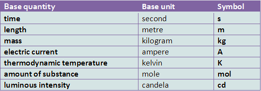
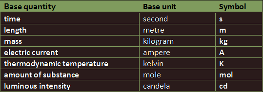
The kilogram is the only base unit with a prefix (kilo).
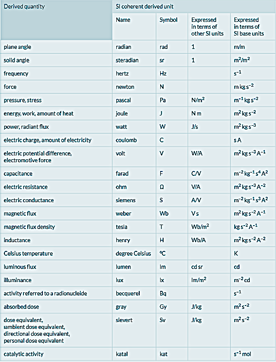
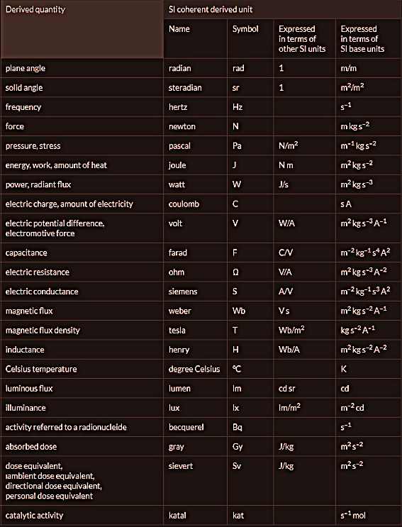
Those SI units which are not base units are called derived units. Derived units are formed by combining base units. Most derived units have been given special names in honour of famous physicists whose research has contributed to our knowledge of the quantity concerned.
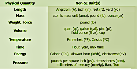
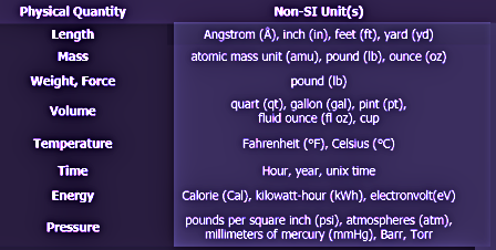
Non-SI units existed long before the invention of SI units. However, these units have been replaced by the standard SI Units in most countries. Some of the commonly used non-SI units are:
Multiples and sub-multiples
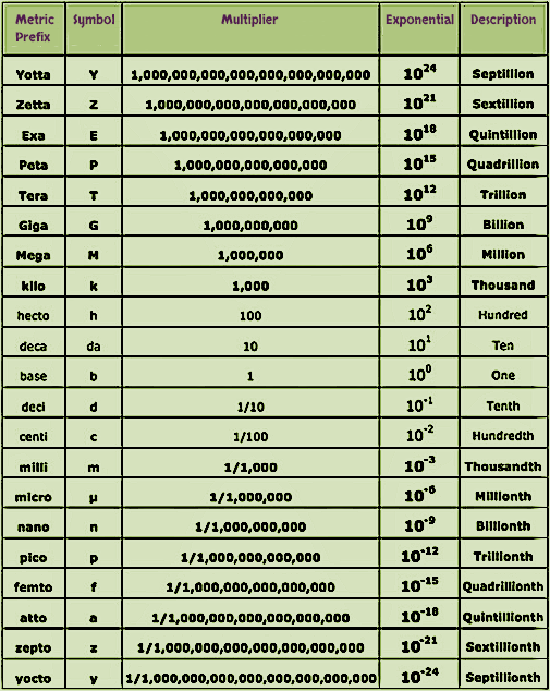
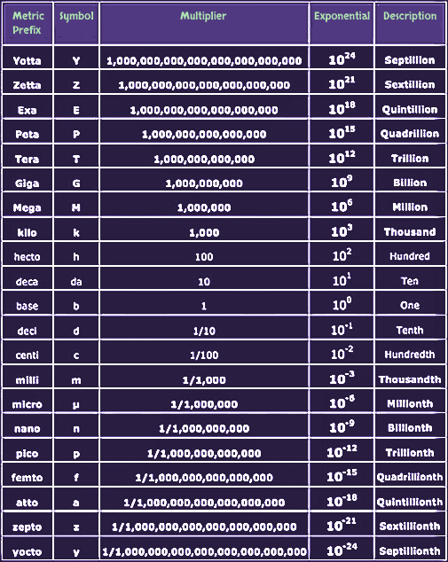
Frequently, we have to deal with very large, or very small, quantities. For example, the resistance of insulation is measured in millions of ohms, while the resistance of a conductor is measured in thousandths of an ohm. To avoid having to express very large or very small values in this way, we use multiples and sub-multiples. These are indicated by assigning a prefix to the SI unit (listed in the table above, on the right).
SI recommends using prefixes employed by the ‘Engineering System’ – i.e. powers of ten which increase or decrease by a factor of three.
Accordingly, units such as the ‘centimetre’, etc., should not be used when working in SI. We cannot insert multiples or sub-multiples into equations. For example, we must always convert microwatts, milliwatts, kilowatts, megawatts, etc., into watts whenever we insert that quantity into an equation.
Electrical schematic and wiring diagrams
Most electrical diagrams fall into two broad categories:
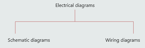
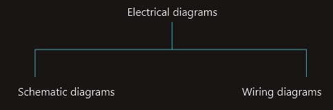
• schematic diagrams (are made as simple as possible and are used whenever we want to design a circuit or whenever we want to understand, or to explain to someone how a circuit works).
• wiring diagrams (on the other hand, tend to be rather more complicated and are used not to show how a circuit works, but how a circuit’s components are physically connected to each other).
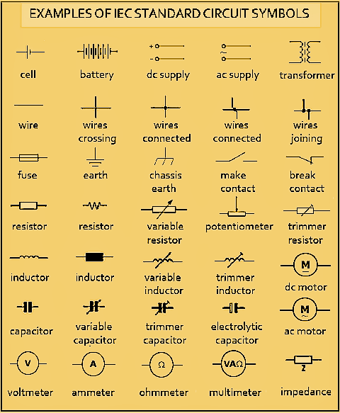
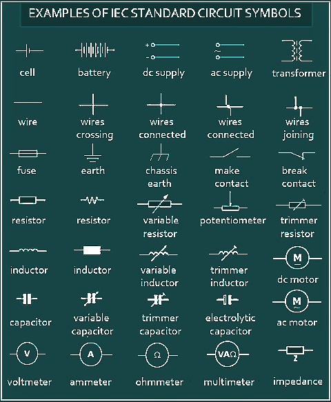 Whenever we create a schematic diagram we should always use standard circuit symbols to represent either the quantities (e.g. resistance, inductance, capacitance, etc.) or the circuit components (e.g. resistors, inductors, capacitors, switches, power supplies, etc.) that we are using in that diagram. Circuit symbols should comply with the relevant international standards. For example, in Europe, we use symbols which comply with standards approved by the IEC (International Electrotechnical Commission). In North America, circuit symbols must comply with standards approved by ANSI/NEMA (American National Standards Institute/National Electrical Manufacturers Association). Other countries may have their own standards but, in many cases, they are based on IEC or ANSI/NEMA standards.
Many of the more-complicated circuit symbols are actually created by simply combining related individual symbols.
Ladder diagrams
With the introduction of the programmable logic controller (a type of industrial digital computer designed for controlling manufacturing processes) in the 1960s, a type of visual computer programming, termed ‘ladder logic’, was developed which has led to the increasing popularity of a type of simplified schematic diagram called a ‘ladder diagram’.
A ladder diagram is a type of schematic diagram in which the voltage supply is represented by two vertical lines, between which the circuit components are connected like the ‘rungs’ of a ladder. We can think of the vertical lines as being the positive and negative (in the case of an a.c. circuit, ‘line’ and ‘neutral’) conductors, termed ‘busbars’, which supply current to the ‘rungs’ of the circuit.
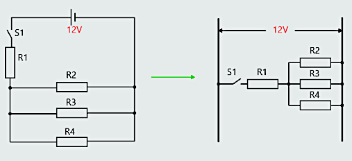
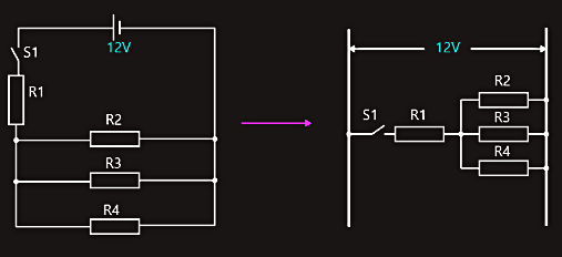 Normally, for a d.c. ladder diagram, the positive vertical line is to the left, and the negative vertical line is to the right. For an a.c. ladder diagram, the energized (‘hot’) line is to the left and the neutral is to the right. Ladder diagrams are normally ‘read’ from left-to-right (so fuses or switches should appear to the left of any particular ‘rung’), and the various components are simply placed according to neatness and how they are electrically connected to each other, not how they are physically located relative to each other.
The 'electron' theory of electricity
Mankind has known about the existence of electricity for thousands of years and most of that time electricity was regarded as either something to be feared (e.g. lightning storms), or simply as a curiosity. Electric current is the quantity of electric charge transported per unit time through a conductor, and the rate at which this charge actually moves is measured in just millimetres per hour. It must be considered whether the circuit is DC, AC or radio waves. Radio waves move at approximately the speed of light, which is 300 000 km/s. The velocity of AC through a conductor is less than the speed of light because magnetic fields travel more slowly in material dielectrics than they do through free air. In the case of alternating current, the charge doesn’t flow at all; it merely oscillates back and forth within the conductor. Yet the transfer of energy along a conductor is close to the speed of light. In DC circuit, the impulse of electricity can appear to be faster than the speed of light.
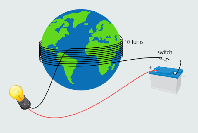
Let's assume for a moment that a pipe has been filled with table—tennis balls.
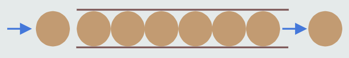
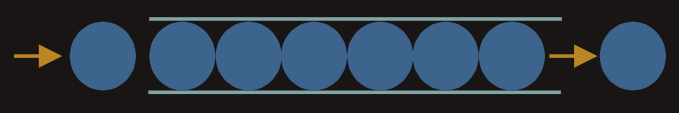
If one ball is forced into the end of the pipe, the ball at the other end will be forced out. Each time ball enters one end of the pipe, another ball is forced out the other end. This principle is also true for electrons in wire. There are billions of electrons in wire. If an electron enters one end of wire, another electron is forced out the other end. Assume that wire is long enough to be wound around the earth ten times. If power source and switch were connected at one end of the wire and light at the other end, the light would turn on the moment the switch was closed. It would take light approximately 1.3 seconds to travel around the earth ten times.
These days, the term ‘electricity’ is used to describe a branch of science in the same way as, for example, we use the word ‘chemistry’, or ‘thermodynamics’, or ‘biology’, or ‘astronomy’, and it is wrong to use it as though it were a measurable quantity, such as charge or current or energy.
By the nineteenth century, despite not really understanding the true nature of ‘electricity’, scientists such as Michael Faraday in Britain, Joseph Henry in the United States, Georg Ohm in Germany, and many others, were establishing ‘rules’ regarding its behaviour, based on the results of their practical experiments.
However, it wasn’t until the gradual accumulation of knowledge on the structure of the atom, from the late nineteenth century onwards, that the secrets of ‘electricity’ finally began to be unravelled.
The problem with atoms is that we can’t ‘see’ them! And without being able to see them, it’s difficult to visualize what they are and how they behave. For something to be visible, it must be capable of reflecting light, and atoms are very much smaller than the wavelength of light and, so, are quite incapable of reflection.
So if we can’t see atoms, how, then, can we possibly know what they ‘look’ like and understand how they behave? The answer, of course, is that we have no idea of what they look like and we still don’t fully understand how they behave! All we can do is try to create an analogy, by comparing it with something that we can describe and understand.
We call this analogy a ‘model’.