


We have seen earlier that in order to cause the 'free' electrons to drift in a given direction, an electromotive force (emf) must be applied. Thus an electromotive force is 'driving' force in an electrical circuit. And whenever current flows through a resistor, there will be a potential difference developed across it. So, an electromotive force is driving force in a circuit that causes current to flow, whilst a potential difference is the result of current flowing through a resistor.
We have analyzed circuits with an ideal source of emf, but in practice that is not the case because of the internal resistance of the source. For example, a typical 12V car battery consists of number of oppositely charged plates, appropriately interconnected to the terminals, immersed in an electrolyte. These all combine together to produce small but finite (measurable) resistance; that is battery internal resistance.
Such battery is shown on the figure below.
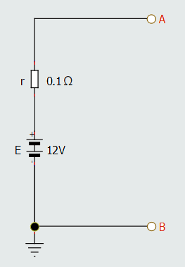
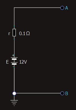
Since the terminals are open, no current can flow, thus there will be no potential difference developed across battery's internal resistance. Potential difference literally means a difference in potential between two ends of r and then the terminal A must be at a potential of 12V, and terminal B at a potential of 0V. Under these conditions, the full emf 12V is available at the battery terminals.
If we now consider the case of the complete circuit where resistor is connected to terminals A and B, then current will flow, which is shown in the next figure.
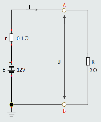
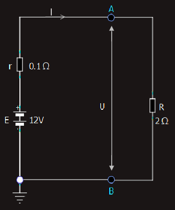
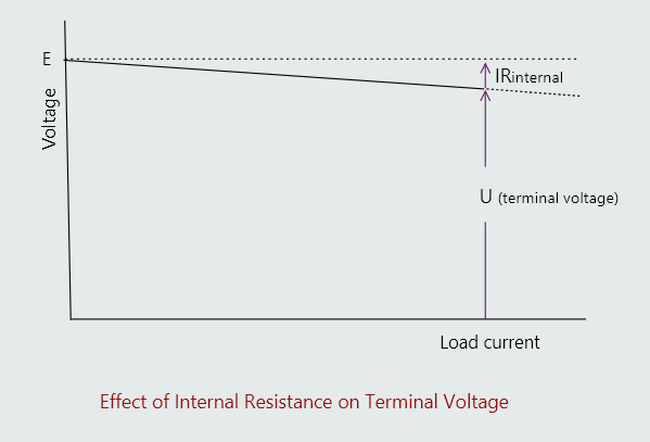
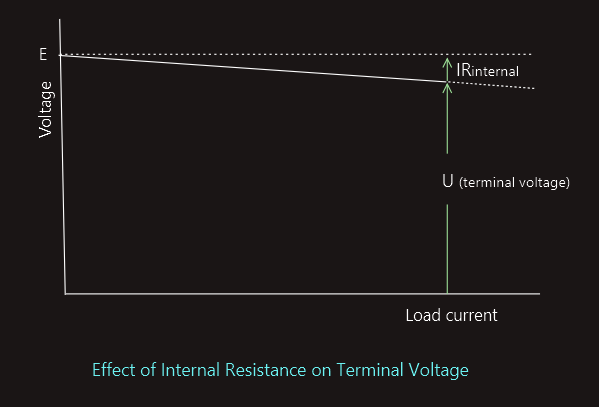
E = I⋅r + U
Using GROUND as a Reference
Two symbols are used to represent ground.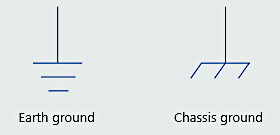
 These are earth ground and chassis ground. Earth ground symbolizes a ground point that is made by physically driving an object such as a rod or a pipe into the ground. Chassis ground is a point that is used as a common connection for other parts of a circuit, but it is not actually driven into the ground. An excellent example of using a chassis ground as a common connection can be found in the electric system of an automobile. The negative terminal of the battery is grounded to the frame or chassis of the vehicle. The frame of the automobile is not connected directly to earth ground; it is insulated from the ground by rubber tires. In the case of an automobile electric system, the chassis of the vehicle is the negative side of the circuit.
Electrical measurements
Today we have a standard and internationally agreed set of units of measurement, and instruments that can measure voltage and current with great accuracy and precision.
We are now going to examine how we detect and measure the three basic electrical quantities: current, voltage and resistance.
To do this, we use an ammeter, a voltmeter and an ohmmeter.


In practice, we are very unlikely to use these individual instruments outside a college laboratory, and it is far more likely that we will use a multimeter, either analogue or digital, which combines the functions of these three separate instruments into one.
Analogue instruments
The ‘moving-coil’, or ‘d’Arsonval’, movement (named after its inventor Jacques-Arsène d’Arsonval) is the most common type of meter movement employed by precision analogue instruments such as ammeters, voltmeters, ohmmeters and multimeters. When meter is made to operate on very small amounts of current, it is often referred to as galvanometer.
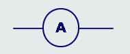
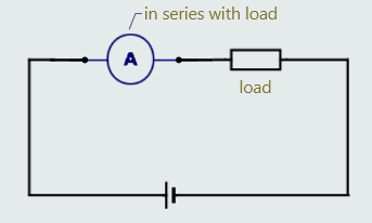
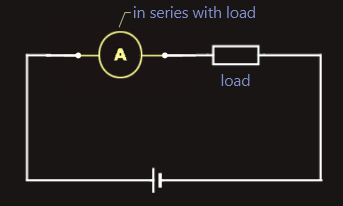
Measuring current: ammeters
To measure current, the circuit should be temporarily disconnected from its supply, and must then be broken at the point where we want that current to be measured, and the ammeter inserted at that point. In other words, an ammeter must be connected in series with the load under test.
It’s very important that the insertion of the ammeter into a circuit has very little effect on the circuit’s existing resistance which would alter the current normally flowing in the circuit and therefore give an inaccurate reading. So, ammeters are manufactured with extremely low values of internal resistance.
Because ammeters have a very low internal resistance, it is vitally important that they are never inadvertently connected across, or in parallel with, any circuit component – and especially with the supply. Failure to do so will result in a short-circuit current flowing through the instrument which may damage the ammeter (although most ammeters are fused) or even result in personal injury.
For multi-range ammeters, we should always start by selecting the highest current range and, then, select whichever range gives the greatest deflection, as this will give us the most accurate reading.
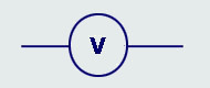
Measuring voltage: voltmeters
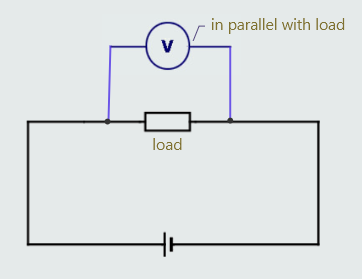
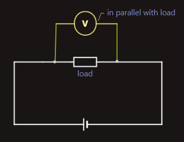
To measure potential-difference, or voltage, a voltmeter must be connected between two points at different potentials. In other words, a voltmeter must always be connected across, or in parallel with the part of the circuit under test.
In order to operate, a voltmeter must, of course, draw some current from the circuit under test to drive its operating coil, and this can lead to inaccurate results because it interferes with the normal condition of the circuit. We call this the ‘loading effect’ and, to minimize this ‘loading effect’ (and, therefore, improve the accuracy of a reading), this operating current drawn from the circuit must be as small as possible and, for this reason, voltmeters are manufactured with a very high value of internal resistance – usually many megaohms.
For multi-range voltmeters, we should always start by selecting the highest range and, then, select whichever range gives the greatest deflection, as this will give us the most accurate reading.
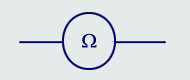
Measuring resistance: ohmmeters
To measure resistance, we use an instrument called an ohmmeter, or we can use the ‘ohms’ range of a multimeter. Ohmmeters also provide us with a convenient way in which to check continuity – that is, to find out whether there are any breaks in a circuit. For example, we might want to check whether or not a fuse has ‘blown’. When checking continuity, we are usually only interested in observing a deflection, and not necessarily the value of the resistance reading. An ohmmeter works by using an internal battery to pass a small test current through the unknown resistance, and measuring the value of that current - the higher the resulting current, of course, the lower the resistance and vice-versa.
Its scale is graduated in ohms and kiloohms. The scale of an ohmmeter differs from that of an ammeter or voltmeter in two very important ways.
Firstly, its scale is reversed – i.e. it reads from right to left – with ‘zero ohms’ corresponding to its full-scale deflection.
Secondly, the scale is non-linear, with its graduations becoming closer and closer together and, therefore, more difficult to read, at the higher values of resistance (i.e. towards the left-hand end of the scale).
When using an ohmmeter, we must always observe the following rules:
(a) - Never EVER connect an ohmmeter to a live circuit – doing so will likely result in a burnt-out instrument, and may cause personal injury.
(b) - Beware of measuring resistance of any component that may be connected in parallel with other components (this is not necessarily obvious), as you’ll end up measuring the combined resistance of all those components! It may be necessary to remove at least one of the component’s connections (e.g. disconnect one end of the resistor from the circuit to which it’s connected).
(c) - When using a multimeter to measure resistance (or to check continuity), it is important to switch the instrument away from its resistance setting (preferably to a current range) when the measurement has been completed. Failure to do so might result in the battery becoming discharged should the test-leads accidentally short circuit during storage.
Analogue multimeters
An analogue multimeter is (usually) a moving-coil instrument that can measure both d.c. and a.c. currents and voltages, together with resistance. Because of their versatility, multimeters are far more widely used in the field than separate ammeters, voltmeters and ohmmeters, which are mainly found in laboratories.
Analogue instruments are undoubtedly more difficult to read accurately, compared with digital instruments, and a certain amount of preparation is necessary in order to use them properly.
We should, therefore, all develop a habit of following these guidelines:
(1) Firstly, all analogue instruments are designed to give accurate readings only when placed in a particular (usually horizontal) position, so they should never be propped-up at an angle, placed vertically or held in the hands – where gravitational forces may act on the pointer to give an inaccurate reading.
(2) Before measuring current or voltage, the pointer must be always checked to ensure it is pointing exactly at zero. If it isn’t, then it must be mechanically adjusted, using a small screwdriver, by means of the zero-adjust screw, located just below the instrument’s scale. We shouldn't confuse this with the zero-ohms adjustment.
(3) Multimeters usually have several scales, corresponding to the different functions and ranges available, as well as for whether we are measuring a.c. or d.c. values. This can be quite confusing, and it’s important to ensure we use the correct function and scale settings when taking a reading.
(4) Multimeters offer different ranges (e.g. voltage ranges offered might be 0 V – 125 V, 0 V – 250 V, 0 V – 500 V). The highest range should always be selected first, but whichever scale then provides the greatest deflection should always be used when taking the actual reading. This is because the accuracy of any instrument is highest at its full-scale deflection, and decreases towards the lower-end of the scale!