


DC Generator
An electrical DC machine can convert mechanical energy into direct current electricity (DC generator) or vice versa (DC motor) without any constructional changes. Thus, a DC generator or a DC motor can be broadly termed as a DC machine.
The DC machine mainly consists of two parts: stator and rotor.
Stator houses the field winding which is the source of magnetic flux in the DC machine.
Rotor contains slots to carry armature windings and provides the rotating element in the DC machine. 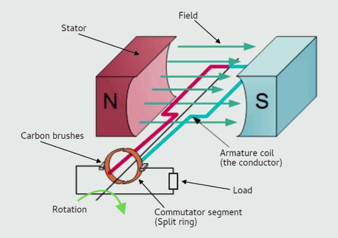
Stator construction
Yoke: An outer frame made up of cast iron or steel to provide mechanical strength and protective covering to the whole machine and also carries the magnetic flux produced by the field winding.
Poles: The magnetic poles are made of thin laminations of silicon steel structures fitted onto the inner wall of the yoke with screws or welding. The pole core carries field winding.
Field winding: Usually made of copper wire and wound over the pole slots and are connected in series. They are wound in such a way that, when energized, they form alternate North and South poles, hence producing magnetic flux.
Eye Bolt: It helps to shift the machine from one place to another or for level change.
Rotor construction
Armature core: It is cylindrical in shape with slots to carry armature winding. The armature core is built up of thin laminated circular silicon steel disks for reducing eddy current losses.
Armature winding: It is usually a former wound copper coil which rests in armature slots. The armature conductors are insulated from each other and also from the armature core.
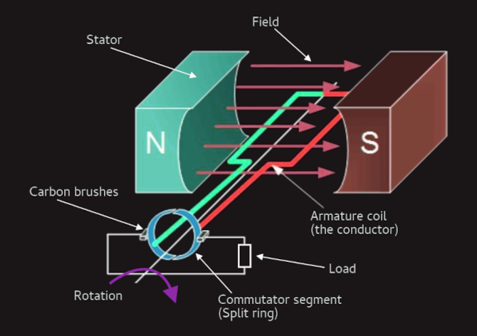
Commutator and brushes: Physical connection to the armature winding is made through a commutator-brush arrangement.
The commutator is made of a set of hard drawn copper segments insulated from each other. The number of segments is equal to the number of armature coils. Each segment is connected to an armature coil and the commutator is keyed to the shaft. Its main function, in a DC generator, is to collect the current generated in armature conductors and change it from internal AC to DC output. A commutator works like a rectifier that changes AC voltage to DC voltage within the armature winding. It is designed with a copper segment, and each copper segment is protected from the other with the help of mica sheets. It is located on the shaft of the machine. Whereas, in case of a DC motor, commutator helps in providing current to the armature conductors that can produce a rotating torque in them.
Brushes are usually made from carbon or graphite. They rest on commutator segments and slide on the segments when the commutator rotates keeping same physical contact.
Using a semicircular commutating segments, whenever current reversal occurs at the armature conductors, the sliding commutator segment reverses connection to the brushes. And therefore, the output at the fixed contacts (brushes) is always built up in the same way resulting in unidirectional DC output current.
Difference between AC and DC Generator
An electrical machine that converts mechanical energy input into electrical energy output is called a generator or electrical generator. There are two types of generators, AC Generator and DC Generator. An AC generator has an electromagnet while a DC generator has a permanent magnet. AC generators have slip rings while DC generators have commutators.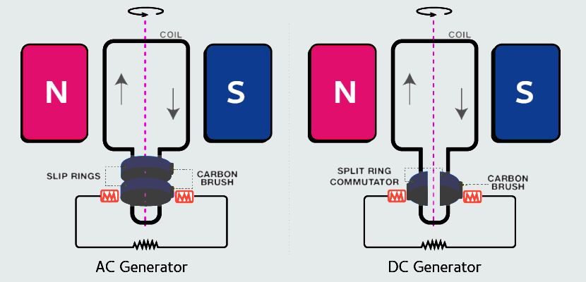
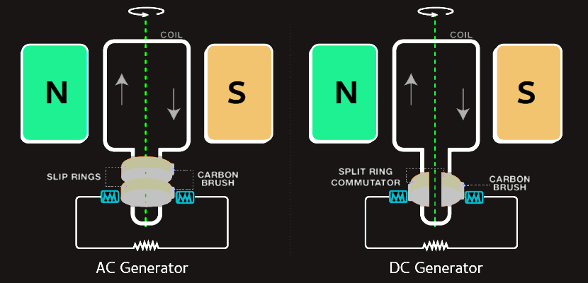
A generator that converts mechanical energy into electrical energy in the form of alternating current is called an AC generator or alternator. The AC generator’s input supply is mechanical energy supplied by steam turbines, gas turbines and combustion engines. The output is alternating electrical power in the form of alternating voltage and current. The electrical energy generated is in the form of an alternating current sinusoidal output wave. Field, armature, prime mover, rotor, stator, and slip rings are the various components of AC generator. The principle on which an AC generator works is Faraday’s law of electromagnetic induction, which states that electromotive force – EMF or voltage – is generated in a current-carrying conductor that cuts a uniform magnetic field. This can either be achieved by rotating a conducting coil in a static magnetic field or rotating the magnetic field containing the stationary conductor. The preferred arrangement is to keep the coil stationary because it is easier to draw induced alternating current from a stationary armature coil than from a rotating coil. When the armature rotates between the poles of the magnet upon an axis perpendicular to the magnetic field, the flux linkage of the armature changes continuously. As a result, an electric current flows through the galvanometer and the slip rings and brushes. The galvanometer swings between positive and negative values. This indicates that there is an alternating current flowing through the galvanometer. The direction of the induced current can be identified using Fleming’s Right-Hand Rule.
A machine that converts mechanical energy into DC electricity is a DC generator. The DC generator uses the principle of energetically induced electromotive force. When the conductor slashes magnetic flux, an emf will be generated based on the electromagnetic induction principle of Faraday’s Laws. This electromotive force can cause a flow of current when the conductor circuit is closed. A DC generator can also be used as a DC motor without changing its construction. Therefore, a DC motor, otherwise a DC generator, can be generally called a DC machine. DC generator works on Faraday’s principle of electromagnetic induction which states that if the conductor is rotated in a magnetic flux, then E.M.F. is generated on that conductor and lasts as long as the conductor continues to rotate. According to this theory - field, conductor, and motion are all three required to generate voltage. So, we know, from Faraday’s law of electromagnetic induction, that when a current-carrying conductor is placed in a varying magnetic field, an emf is induced in the conductor. According to Fleming’s right-hand rule, the direction of the induced current changes whenever the direction of motion of the conductor changes. Let us consider an armature rotating clockwise and a conductor at the left moving upwards. When the armature completes a half rotation, the direction of the motion of the conductor will be reversed downward. Hence, the direction of the current in every armature will be alternating. But with a split ring commutator, connections of the armature conductors get reversed when a current reversal occurs. Therefore, we get a unidirectional current at the terminals.
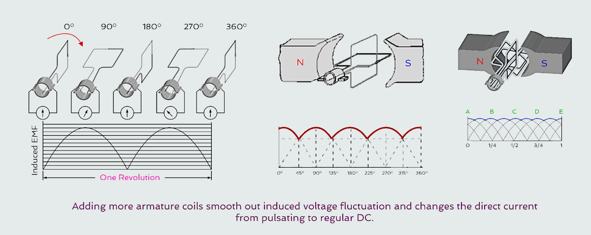
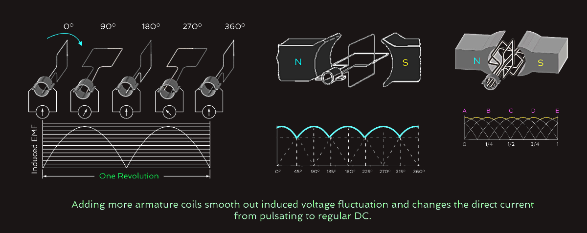 Practical generators use many armature coils. They also use more than one pair of magnetic poles. The additional magnetic poles have the same effect on ripple as did the additional armature coils. In addition, the increased number of poles provides a stronger magnetic field (greater number of flux lines). This, in turn, allows an increase in output voltage because the coils cut more lines of flux per revolution.
The losses that occur in DC machines can be divided into four basic categories:
1. Electrical or copper losses
2. Core or magnetic losses
3. Mechanical losses
4. Stray load losses
DC generators can be separately excited and self excited.
In the first type, field coils are energized from a separate external DC source. That is, field winding is electrically separated from the armature circuit.
In the second type, field coils are energized from the current produced by the generator itself. Initial emf generation is due to residual flux in field poles. This generated emf causes a part of current to flow in the field coils, thus strengthening the field flux and thereby increasing emf generation.
Field winding and armature winding are interconnected in various ways to achieve wide range of performance characteristics...