


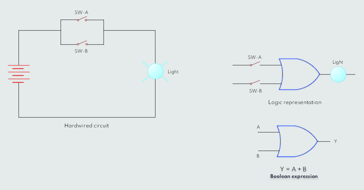
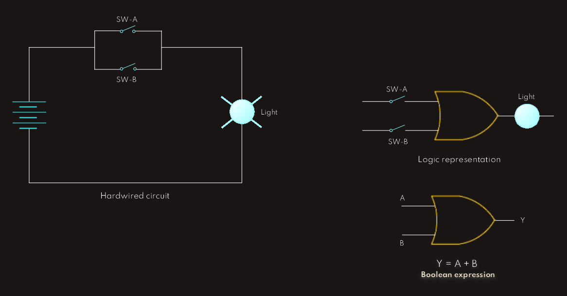
The OR Function
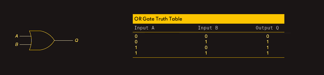
An OR gate can have any number of inputs but only one output. The OR gate output is 1 if one or more inputs are 1, otherwise it is 0. 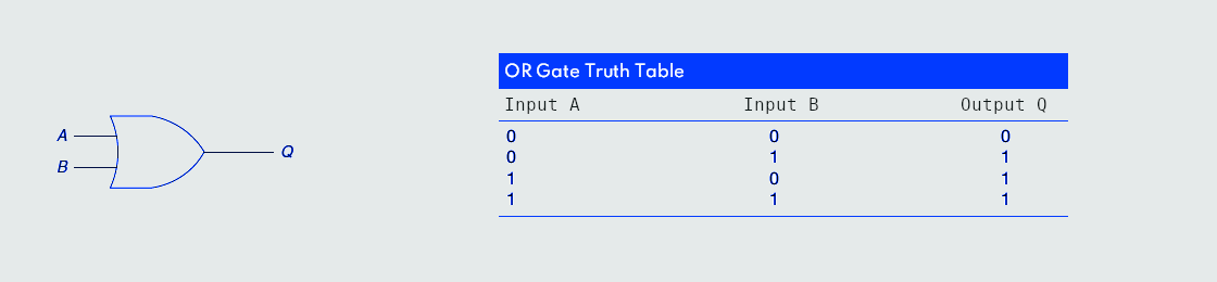
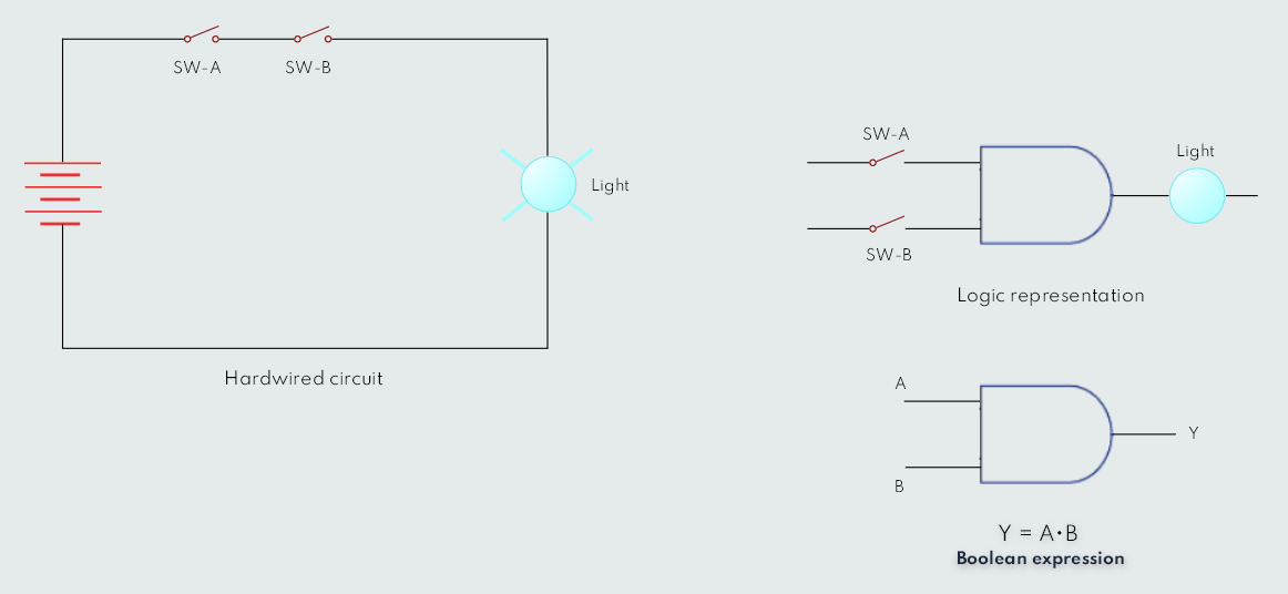
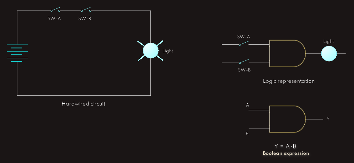
 The OR logic gate operates similarly to control devices connected in parallel. The light will be on if switch A or switch B or both are closed.
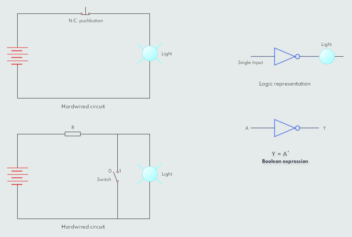
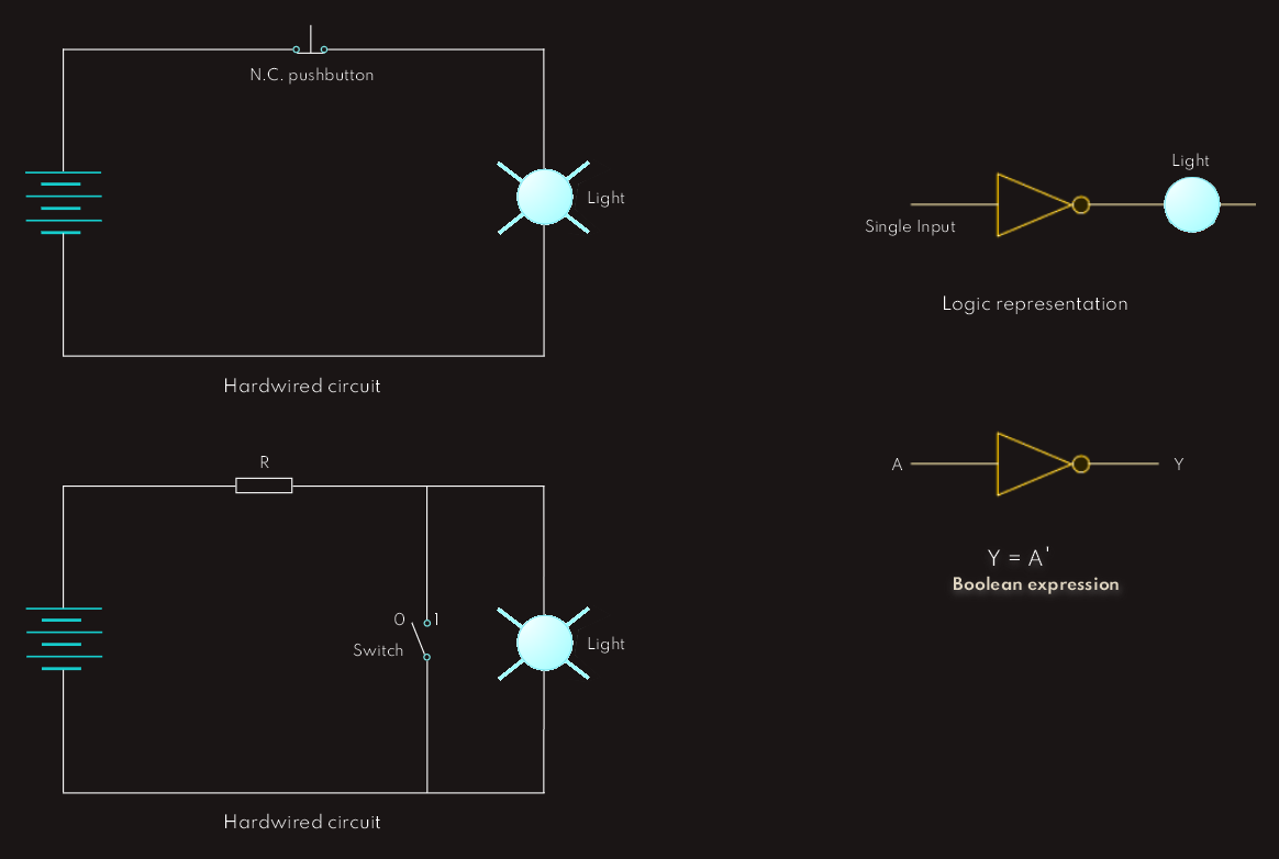
The NOT Function (Inverter)
The NOT function, unlike AND and OR functions, can have only one input. The NOT output is 1 if the input is 0; the output is 0 if the input is 1. The result of the NOT operation is always the inverse of the input, and the NOT function is, therefore, called an inverter. 
 The logical NOT function can be performed on a contact input by using a normally closed instead of a normally open contact. When the input pushbutton is not actuated, the output lamp is ON. When the input pushbutton is actuated, the output lamp switches OFF.
Another way for using the logical NOT function is illustrated on the second circuit - when the switch is closed, the current takes the path of least resistance and the light goes OFF, and when the switch is open, then the current through this branch cannot flow, it goes through the light branch and the lightbulb goes ON.
So, here on both examples, we have, let's say inversion method.
NAND Gates
NAND gate outputs are inverse of those in AND gate, so it can be thought as an inverted AND gate. 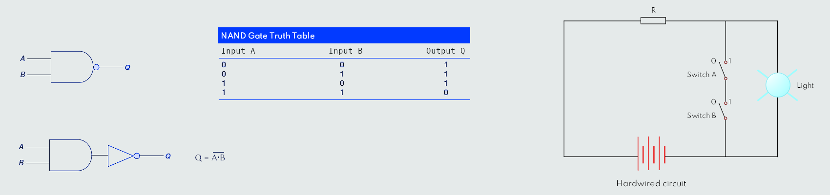
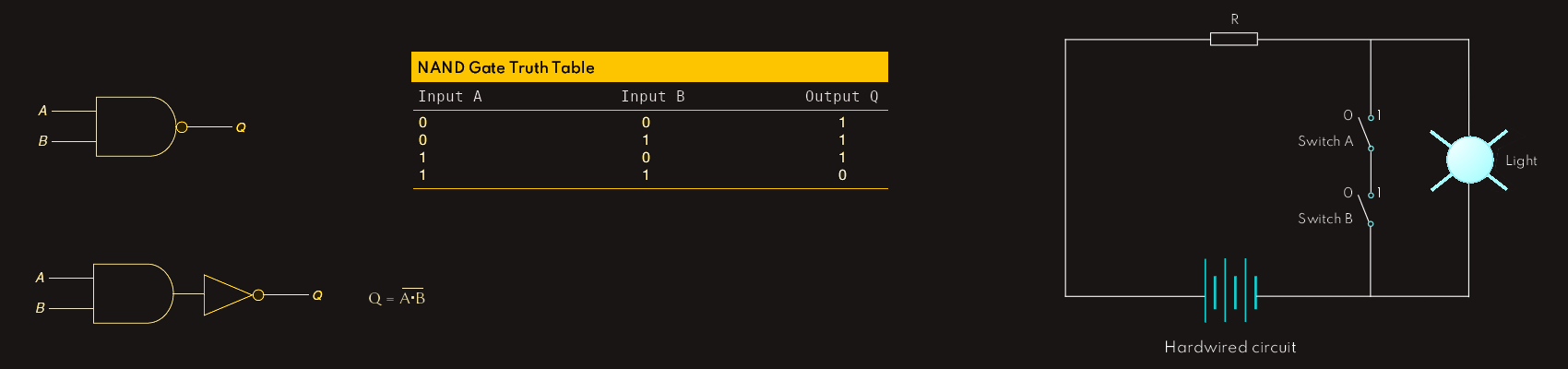 The lamp will be off when both switches are closed.