


Power Frequencies
There is no fundamental physical law that states that AC power must be generated at 60 Hertz; it was initial design decision by Tesla. In fact, many parts of the world use 50 Hertz as the AC generation frequency. However, it’s possible to generate any desired frequency of AC waveform with a properly designed generator. The two main power frequencies used across the globe are 50Hz or 60Hz, and the majority of countries favour a 50Hz frequency for their mains supply, though there are still a significant number of countries using a 60Hz supply.
We might initially assume that the mains power supply would be the same wherever we go, but it simply isn’t the case. It all dates back to the late 1880s when Thomas Edison and Nikola Tesla had conflicting ideas about bringing electricity into homes across New York. Edison wanted to use Direct Current (DC), whereas Tesla proposed the use of Alternating Current (AC). Tesla declared the best frequency to use was 60Hz at 240 volts, whereas Edison relied on a lower voltage system of around 110 V. Not wanting to lose out to his competitor, Edison spread his opinion that 240 volts was far too high for use in the home and many local residents agreed, believing it would be too dangerous. Edison’s scaremongering worked, though the decision ultimately went in Tesla’s favour, with New York adopting an AC supply at 110 volts and 60Hz.
Word soon spread and other countries began implementing their own mains power supply; however, some companies in Europe controversially decided to go with 50Hz rather than 60Hz. We’ve now got the US running their power supply at 60Hz and the majority of Europe using 50Hz – but it doesn’t end there - complicating things further, several countries in Europe then began implementing their 60Hz power supply systems in their colonies across Asia and Africa. Interestingly, the frequency in Japan isn’t even uniform across the country! Areas in the east, like Tokyo, operate on 50Hz, whereas areas in the west like Osaka and Kyoto use a 60Hz power supply.
As no international standard was ever set, countries all over the world have their initial frequencies and here we are, over 100 years later!
There are a number of reasons why the frequency of a mains supply is regulated, but the main one is to prevent damaging equipment or infrastructure. All equipment will be designed for use in a specific country, and so manufacturers will create their products to run at the correct frequency for the country they’re being sold or used in. When travelling overseas we’re likely to come across a mains supply that is different from our home country. Unfortunately, this means that we won’t be able to utilize equipment that requires a 60Hz power supply in a country that runs a 50Hz power supply. Running equipment at the wrong frequency can severely damage it; which is why we use frequency converters that can transform 50Hz to 60Hz and 60Hz to 50Hz to suit all countries.
AC power distribution
Industrialization in the early 1900s drove the rapid expansion of electrical transmission lines to connect power generation plants with end stations. Generation plants would create electrical power at very high voltages to transfer it more efficiently over the lines, and in order to use it on the other side, it had to be lowered before reaching their destinations, which was accomplished by using transformers.
An electrical transformer is a device that transforms an AC waveform from one amplitude to another. As AC is applied to the primary side of the transformer, the electrical energy transforms into magnetic energy in the same way as that of an inductor. The inducted magnetic energy travels through the iron core of the transformer and through the other loop of wire, known as the secondary. This magnetic energy converts back into electrical energy creating an electrical current through the secondary wire.
It is important to note that the conversion process from electrical, to magnetic, and back to electrical only works for alternating current.
If the current instead was direct, it would not induce the magnetic field needed to transform the energy to the secondary side of the transformer.
A transformer is designed to step-up or step-down a voltage in a wire to make transferring electricity more efficient. To do this they contain two isolated coiled wires. The electromotive force in the primary coil drives an alternating current through the wire inducing a magnetic field. As the size and strength of a magnetic field is proportional to the current, the magnetic field constantly changes expanding and contracting as the current alternates. The magnetic field lines intersect the secondary coil of wire during the expansion and contraction, which causes the reverse to occur, where a magnetic field induces an EMF and current in the new wire without them being physically connected.
As a direct current is constant, the magnetic field produced would not move and the field lines would not intersect the secondary wire resulting in no induction of EMF or current. Hence, transformers only work on alternating current. The current in the primary coil causes it to become an electromagnet. The continually changing current produces a continually changing magnetic field in an iron core. This in turn induces a continually changing voltage in the nearby secondary coil wound round the iron core. A transformer won't work on direct current because a stationary magnet will only produce a steady magnetic field - and steady or stationary magnetic fields do not induce voltages; changing electric current can induce a magnetic field, and vice versa, which is the principle of electromagnetic induction.
The size of the induced voltage depends on the number of turns on each coil – if there are less in the secondary coil, the voltage falls, and if there are more in the secondary coil, the voltage rises.
Three-phase power
Power generation at power plants usually is a three-phase system. This means that instead of a single waveform, the power company generates three different waveforms. Each waveform looks the same, but is slightly offset in time from the other two. The only thing special about three-phase power is that we’re sending out three different AC waveforms, on three different wires - each slightly offset from each other in time. In the home, generally only one of these phases is needed to supply the basic power needs. However, all three phases become important when dealing with industrial equipment. 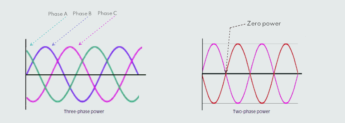
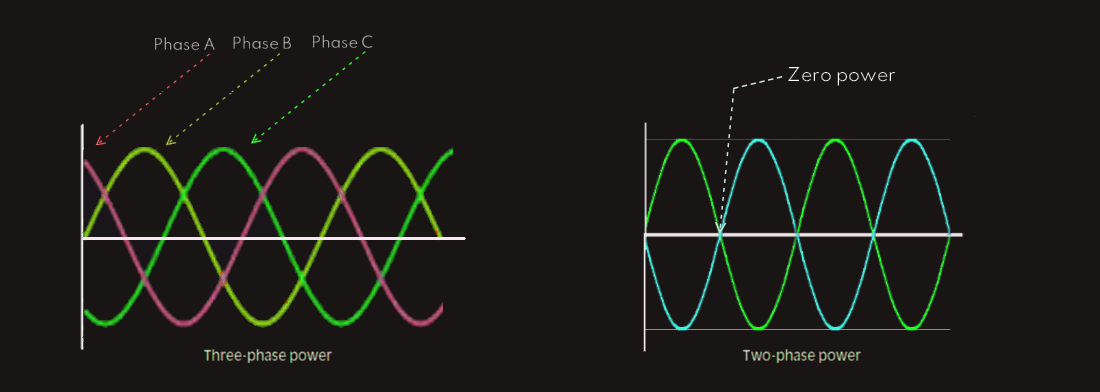 With both one and two phase (180 degrees phase-shift) power, there is a period of time at which the AC waveform is passing through zero. If some machinery is using single phase power, for example, as the voltage crosses through zero the instantaneous power consumption of the machine is also zero. This scenario is acceptable when working with light bulbs, for example, as the light flicker is not noticeable. However, some industrial equipment is not as "tolerant". In these pieces of equipment, certain electrical parts may exhibit bad effects when presented with electrical power that goes “off” periodically. The power delivered to these machines as a result of one phase AC is not smooth and steady, and it may cause a reduction in their expected lifetimes.
With three phases of AC, there is no time period in which the instantaneous power consumption of the connected machine is at zero. Any time one of the waveforms is passing through zero another one is reaching its peak. A machine that can utilize three phase power has a more even distribution of power. One very common use of 3-phase power is specially designed electric motors.
We can now have a question why three phases and not four or more phases? It comes down to cost. The cost of adding yet another wire for the power company to run is significant. The overall cost was higher than any other efficiency gains it might bring to 4-phase motor design. Three phases became a natural settling point.
The three phases of power leaving the electrical company’s generators are in the thousands of volts. In order to be transmitted long distances efficiently, the power company uses step-up transformers to convert these voltages to hundreds of thousands of volts. These high voltage wires can be seen hanging from large towers. The high voltage lines eventually reach sub-stations, where they are stepped back down for further distribution, and to its destinations along utility poles or buried cable. The reason for lines on the high towers for high voltages is because the amount of insulation required to cover the wires to keep them from touching the ground would be financially impractical. Also, the wires would have to be buried very deep in order to keep someone from digging into them. And finally, if there is an electrical issue, such as a broken wire, it’s much easier to fix a wire that is exposed instead of one we cannot easily see where the break might be.
Each commercial residence and business that uses electrical power has a transformer dedicated to its electrical service. This transformer takes the distribution voltage and converts it to the voltage utilized by the consumer. A home service transformer is actually designed to deliver both 240VAC and 120VAC through a special transformer tap arrangement as shown below. ![]()
![]() The secondary side of the transformer has an extra wire that is connected halfway into the secondary windings. To utilize 240VAC, the two ends of the secondary side of the transformer are used as normal. To get 120VAC, the center wire is used along with one from either end of the transformer.
The secondary side of the transformer has an extra wire that is connected halfway into the secondary windings. To utilize 240VAC, the two ends of the secondary side of the transformer are used as normal. To get 120VAC, the center wire is used along with one from either end of the transformer.
Ground
Historically, ground represents the physical earth. As electrical systems were being developed, it was found that the earth is an electrically neutral body. Since voltage is measured as the potential difference between two points, having a common frame of reference is important. Now, a ground can be a more generic term for a common frame of reference for voltage measurements within a circuit, even though it may not be related to the earth itself.
When talking about voltage, which is the potential difference created by an electrical field, this difference has to be between two things. If this voltage is created by a battery, for example, the battery has to have two terminals. The potential difference between these two terminals is what creates the electricity. When wire is connected to these terminals and electrical components are activated at the ends of the wire, current flows out of one terminal and through the components back into the other terminal. The loop has to be complete in order for the current to flow.
If we had multiple batteries, we would need multiple sets of wires for each. But, it is possible for multiple energy sources, like batteries, to share the same return path. Using a common return path for multiple sources saves on parts cost and makes the circuit easier to understand. When we refer to a signal ground, what we are usually referring to is the return path for small voltage sources, like small batteries or other small electrical signals. In many cases, it makes sense to connect one side of all of our voltage sources together to the common signal ground. This helps to commonize all of our voltage measurements to one single reference point.
Earth ground
An earth ground is an electrical connection to the earth - which is a good conductor, to provide a return path for current. Antennas and metallic towers, such as those used for cellular phones, are directly connected to the earth ground. This means that if they were to ever be hit by lightning, the resulting current would have a place to go. As well, lightning rods on houses and other buildings are generally earth grounded to copper rods driven into the earth, as regulation rules dictate. Our feet for example may be earth grounded, which means that if our body was to come into contact with electricity, electricity would have a place to go.
Since as humans we are frequently in contact with the earth and the human body can conduct electricity, there is some danger when we come into contact with other conductors. When we touch some conductor in our house, for example copper water pipe, our body completes a path for the current to travel, since we also are probably earth grounded. As a result, we get a serious jolt of electricity. Luckily, electrical code regulations specify that there must be earth ground at some central point. This means that the current in any stray electrical wire that touches the pipe in our house would have a place to go - through the pipe and into the ground, most likely tripping a breaker or blowing a fuse. Because the copper pipes are connected to earth ground, they are at the same electrical potential as the ground. If we have one hand on a pipe and one foot on the ground, no current can flow into our body because the electrical potentials between our hand and foot are the same.
All grounded buildings, having a connection to earth’s ground built in nearby, generally by cca 2.5m piece of copper pipe driven into the earth, are protected - ground plug at each of the electrical outlets in the home connects back to this earth ground. In turn, all appliances with exposed metallic parts connect to this ground plug, which ensures that there are no exposed metallic elements in the home that could potentially be a source of electrocution should a stray current carrying power line come into contact with them.