


A series-parallel circuit combines series and parallel elements which can be easily resolved into an equivalent series circuit and, ultimately, to a single component.
There’s an infinite number of such combinations.
The term ‘complex circuit’ doesn’t necessarily mean that the circuit is complicated (although it very often is!), but is simply the term given to a category into which we can put any circuit that isn’t either a series circuit, a parallel circuit or a series-parallel circuit. Again, there is an infinite number of examples of complex circuits - they require special techniques (called ‘network theorems’) to solve them and they cannot be simplified using the techniques explained here.
Any electrical components may be connected in the ways described above.
Since most electrical components have resistance, we will now consider the effect of connecting resistances in series, parallel and in series-parallel.
In circuit diagrams arrows are used to represent the ‘directions’, or ‘sense’, in which potential differences act and currents flow. We call these arrows ‘sense arrows’, and they help us form a ‘mental picture’ of the ‘direction’ or ‘sense’ in which the potential differences and currents act in any given circuit at any given instant in time. Even though we have learnt that, in metallic conductors, electric current is a flow of free electrons from a negative potential to a positive potential, it has been traditional to show ‘conventional flow’ (positive to negative) in circuit diagrams. With conventional flow, a positive potential is considered to be a ‘higher’ potential than a negative potential.
Voltage-source sense arrows
For potential differences, a single-headed sense arrow is used. The arrow head always represents the higher (positive) potential of a voltage source (E).
Current and voltage-drop sense arrows
For current, an arrow placed in the circuit always points in the direction of conventional current flow (positive-to-negative). For current to flow through individual circuit components, such as resistances, there must be a difference in potential across each of those components. We call this difference in potential, a voltage drop (U1, U2, etc.). The arrowhead for a sense arrow representing a voltage drop always points towards the higher (positive) potential – or in the opposite direction to the current sense arrow.
The sense of each voltage drop, U1, U2, U3, etc. act in the opposite sense to the potential difference E, across the source (battery), which agrees with Kirchhoff’s Voltage Law.
Kirchhoff’s Laws
Two laws that describe the behaviour of voltages and currents in all electric circuits, are called, respectively, ‘Kirchhoff’s Voltage Law’ and ‘Kirchhoff’s Current Law’, and they are both credited to the Prussian physicist, Gustav Kirchhoff (1824–1887) who established them while he was still a university student!
Kirchhoff’s Voltage Law
Kirchhoff’s Voltage Law states that, ‘for any closed loop, the sum of the voltage drops around that loop is equal to the applied voltage’.
A ‘voltage drop’ is the potential difference that appears across a component, such as a resistor, and which drives current through that component (U = IR).
It can be also expressed as: ‘In any closed loop, the algebraic sum of the voltages is zero’.
Let's take a look at this simple series circuit:
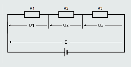
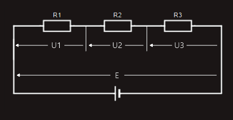
There is only one 'closed loop', so for voltage drops across resistors and applied voltage, we would find:
E = U1 + U2 + U3.
We will now analyze another, more complicated example:
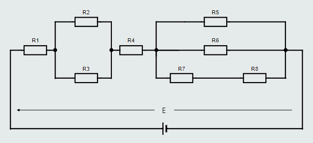
For our purposes, a ‘closed loop’ is any route around the circuit from the battery’s positive terminal to its negative terminal.
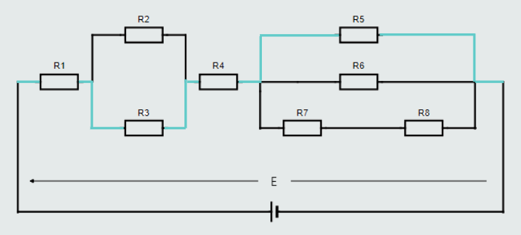
Let’s examine the first ‘closed loop’ shown in orange color wire connecting resistors R1, R2, R4, R5:
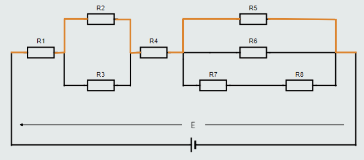
If we were to measure the voltage drop across each resistor in this particular ‘closed loop’ and compare them with the applied voltage, we would find: E = U1+U2+U4+U5.
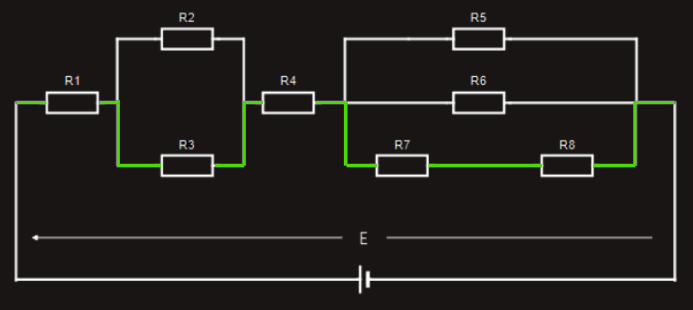
Let’s now look at a different ‘closed loop’ through the same circuit, shown in violet color wire connecting resistors R1, R3, R4, R6:
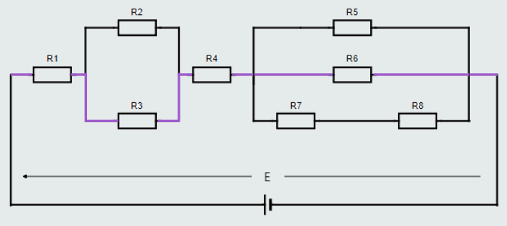
Again, if we were to measure the voltage drop across each resistor in this particular ‘closed loop’ and compare them with the applied voltage, we would find: E = U1+U3+U4+U6.
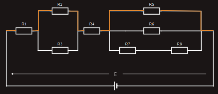
Next, let’s look at yet a different ‘closed loop’ through the same circuit, which includes resistors R1, R3, R4, R7, R8 connected with a green color wire.
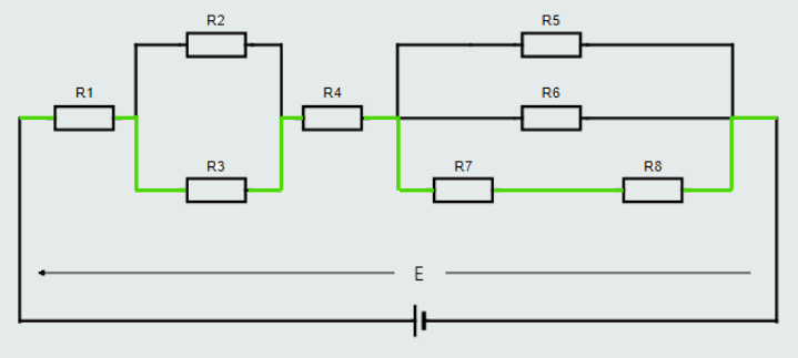
Once again, if we were to measure the voltage drop across each resistor in this particular ‘closed loop’ and compare them with the applied voltage, we would find: E = U1+U3+U4+U7+U8.
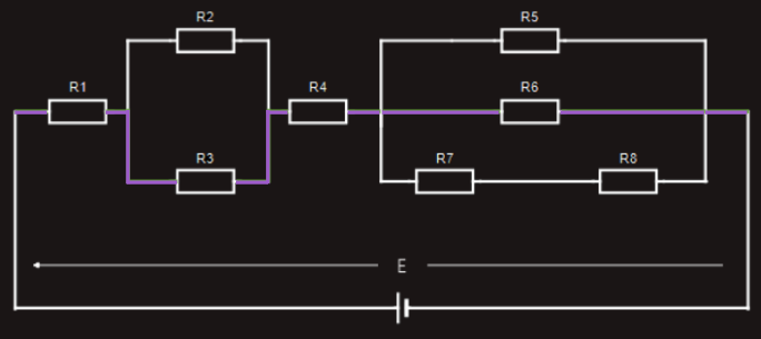
Finally, let’s look at the ‘closed loop’, formed by R1, R3, R4, R5 connected with a blue color wire.
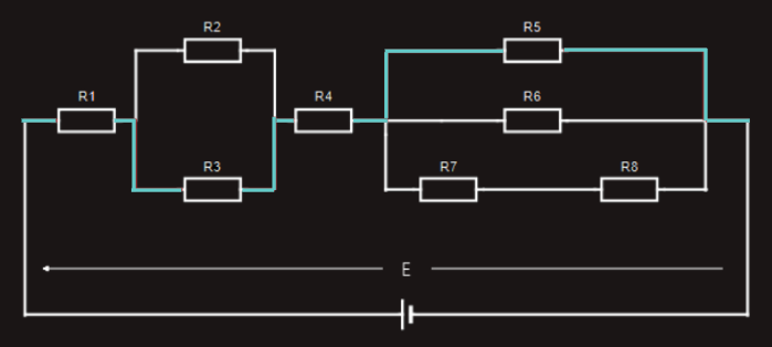
If we were to measure the voltage drop across each resistor in this particular ‘closed loop’ and compare them with the applied voltage, we would find: E = U1+U3+U4+U5.
From each of the above examples, we see that it doesn’t matter which ‘closed loop’ route we take around any electric circuit, the sum of the voltage drops around that particular loop will always equal the applied voltage.
Kirchhoff’s Current Law
Kirchhoff’s Current Law states that ‘the sum of the individual currents approaching a junction is equal to the sum of the currents leaving that junction’.
It can be also expressed in the following form: ‘At any junction, the algebraic sum of the currents is zero’.
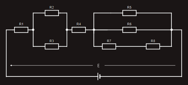
Let's examine another series-parallel circuit for the purpose of understanding this law:
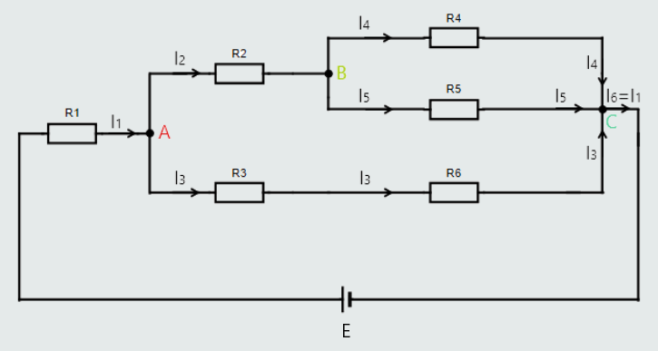
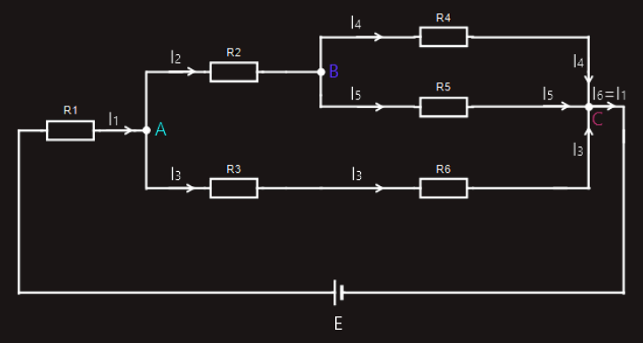
There are three ‘junctions’ in this circuit, labelled A, B and C.
At junction A, the current (I1) approaching that junction is equal to the sum of the two currents, I2 and I3, leaving that junction.
I1 = I2+I3
At junction B, the current (I2) approaching that junction is equal to the sum of the two currents, I4 and I5, leaving that junction.
I2 = I4+I5
At junction C, the sum of the three currents (I3+I4+I5) approaching that junction is equal to the current, I6, leaving that junction.
I3+I4+I5 = I6
And, of course, current I6 is exactly the same current as I1.