


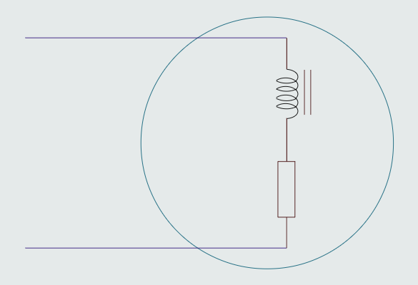

Electric motor is a good example of R-L series circuit. The motor winding is basically an inductor. It is a coil of wire surrounded by an iron core. The wire does have resistance, however. Since there is only one path for current flow through the circuit, it is a series circuit.
When a motor is operated at no load, it will have a large inductive component as compared to resistance. As load is added to the motor, electrical energy is converted into kinetic energy causing an increase in true power or watts. This has the effect of increasing the amount of circuit resistance. When a motor is operated at full load, the circuit has become an R-L series circuit with more resistance than inductance.
Although an AC motor is an inductive device, when it is loaded it must produce true power to overcome the load connected to it. As load is added to the motor, more electric energy is converted into mechanical energy to drive the load.
R-L parallel circuit
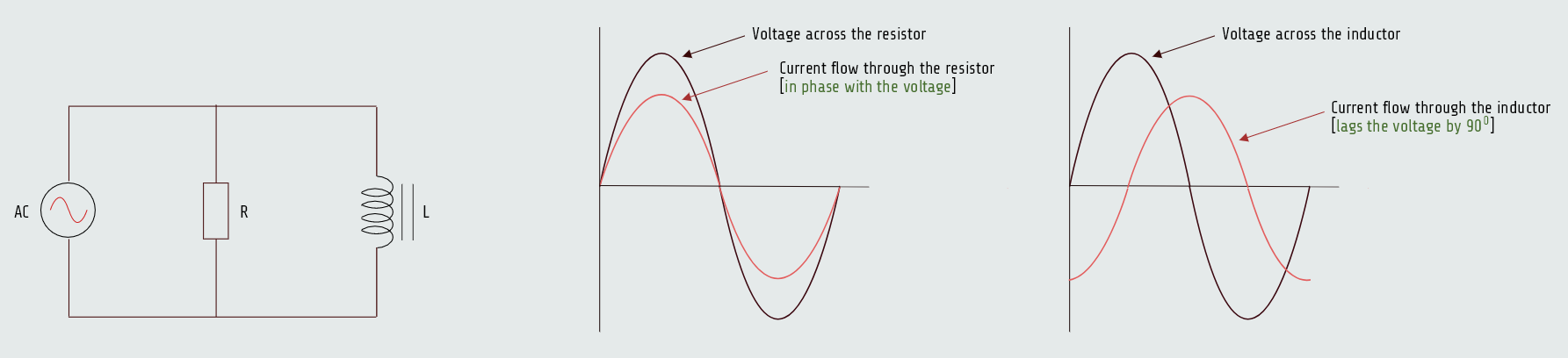
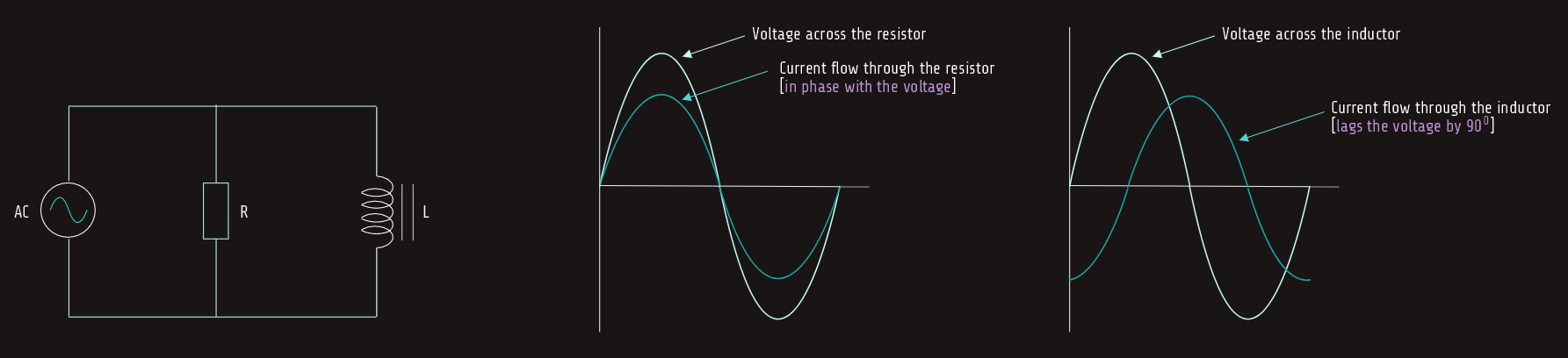
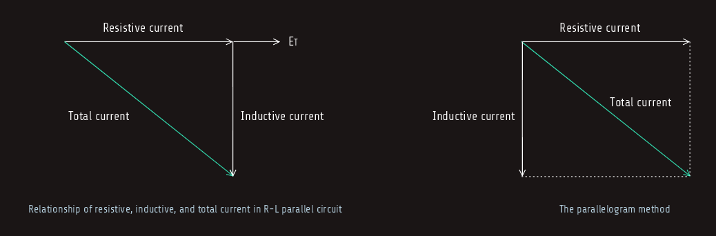
We know by now that the voltage applied to any device in parallel must be the same, so the voltage applied to the resistor and inductor must be in phase and have the same value. The current flow through the inductor will be 90° out of phase with the voltage, and the current flow through the resistor will be in phase with the voltage. This configuration produces a phase angle difference of 90° between the current flow through a pure inductive load and a pure resistive load. The amount of phase angle shift between the total circuit current and voltage is determined by the ratio of the amount of resistance to the amount of inductance. The circuit power factor is still determined by the ratio of true power to apparent power.
Let's say that the resistance of 15 ohms is connected in parallel with an inductive reactance of 20 ohms. The circuit is connected to a voltage of 240 volts AC and a frequency of 60 hertz, and we will calculate different circuit values in the following analysis.
Resistive current
Here we have 240 volts applied across both the resistor and the inductor. Since the amount of voltage applied to the resistor is known, the amount of current flow through the resistor can be computed using formula:
IR = E/R
IR = 240/15 = 16 [A]
True power
True power (watts) can be computed using any of the watts formulas and pure resistive values:
P = ERxIR
P = 240x16 [W] = 3840 [W]
Inductive current
Since the voltage applied to the inductor is known, the current flow can be found by dividing the voltage by the inductive reactance:
IL = E/XL
IL = 240/20 = 12 [A]
VARs
The amount of reactive power is:
VARs = ELxIL
VARs = 240x12 = 2880
Inductance
The inductance of the coil can be found using the formula:
L = XL/2πf
L = 20/(2·3,14·60) = 0,0531 [H]
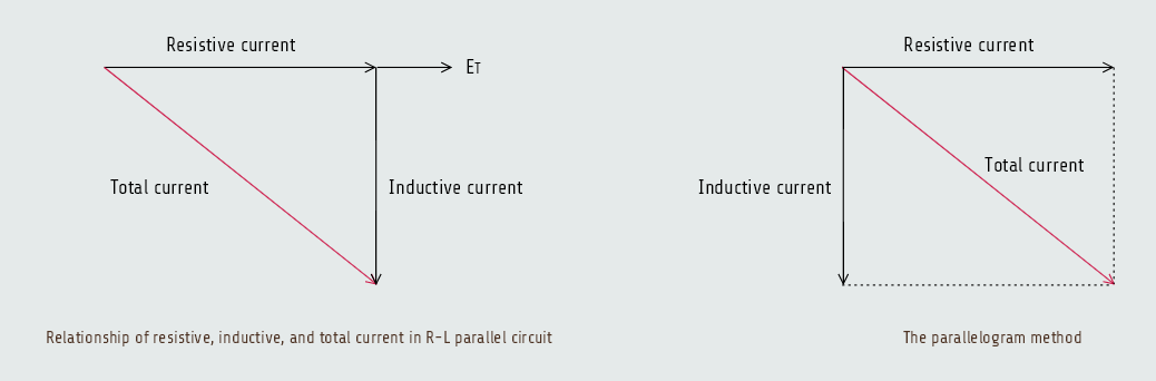
Total current
The total current flow through the circuit can be computed by adding the current flow through the resistor and the inductor. Since these two currents are 90° out of phase with each other, vector addition is used. The current flow through the resistor and inductor form the legs of a right triangle and the total current is the hypotenuse.
IT = √(IR2+IL2)
IT = √(162+122)
IT = 20 [A]
Impedance
The total impedance (Z) can be computed by substituting Z for R in an Ohm’s law formula, since we now know both the total circuit current and the total voltage.
Z = E/IT
Z = 240/20 = 12 [Ω]
The value of impedance can also be found if total current and voltage are not known. In a parallel circuit, the reciprocal of the total resistance is equal to the sum of the reciprocals of each resistor. Since we have here resistor and inductor, which are 90° out of phase with each other, we must use vector addition in formula:
(1/Z)2 = (1/R)2+(1/XL)2
And, also another formula can be used:
Z = (R x XL)/√(R2+XL2)
Apparent power
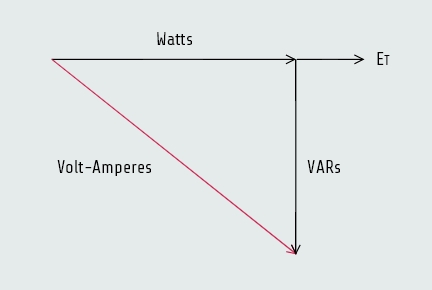
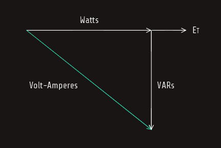
The apparent power (VA) can be computed by multiplying the circuit voltage by the total current flow. The relationship of volt-amperes, watts, and VARs is the same for an RL parallel circuit as it is for an RL series circuit, because power adds in any type of circuit. Since the true power and reactive power are 90° out of phase with each other, they form a right triangle with apparent power as the hypotenuse.
VA = ETxIT
VA = 240x20 = 4800
Power factor
There are some differences in the formulas used to compute power factor in a parallel circuit comparing to series circuit. In an R-L series circuit, power factor could be computed by dividing the voltage dropped across the resistor by the total, or applied, voltage. In a parallel circuit, the voltage is the same but the currents are different. Therefore, power factor can be computed by dividing the current flow through the resistive parts of the circuit by the total circuit current:
PF = IR/IT
Also, in a parallel circuit, the total circuit impedance will be less than the resistance. Therefore, if power factor is to be computed using impedance and resistance, the impedance must be divided by the resistance:
PF = Z/R
In our example we will use formula PF = P/VA , though:
PF = 3840/4800 = 0,80
PF = 80 %