


The energy in the universe exists in various forms, such as heat energy, light energy, and electric energy. When we say we “use” electric energy, we do not mean that we have destroyed, or lost, the energy. We mean that we have converted that electric energy into a more useful form of energy. For example, when we operate an electric lamp, we are converting electric energy into light energy and heat energy. We have used the electric energy in the sense that it no longer exists as electric energy, but we have not used up the energy. It still exists as heat energy and light energy. A light bulb converts electric energy into light energy and heat energy. Another familiar object that converts energy is the electric stove, which converts electric energy to heat energy. Changing electric energy to mechanical (rotational) energy with an electric motor is also a common conversion.
It takes a whole lot of energy to power the world as we know it. Annual energy consumption globally is estimated to be 580 million terajoules – equivalent to 13865 million tons of oil equivalents. Scientists have sounded the alarm on global warming for a long time. Still, in recent years the disturbances to our global climate have resulted in extreme weather events that have been impossible to ignore. For businesses looking to do their part through decarbonization, optimizing energy efficiency is one of the most cost-effective ways to go about it.
Energy efficiency is often reduced by devices and equipment being left on when not in use, charged while at full battery capacity, or otherwise drawing power from the electrical grid.

 For example - an older piece of equipment receives 500 joules of power to produce the equivalent of 100 joules of output; 100/500 = 0.2, or 20% efficiency.
A newer equipment version takes the same 500 - joule input to generate 400 joules of productive output; 400/500 = 0.8, or 80% efficiency — much better!
In some cases, the “wasted” energy will result in a byproduct that can be utilized, such as the heat generated by lamps that are primarily designed to illuminate. If we can’t capture that energy, it simply disperses itself and provides no benefit.
Voltage source
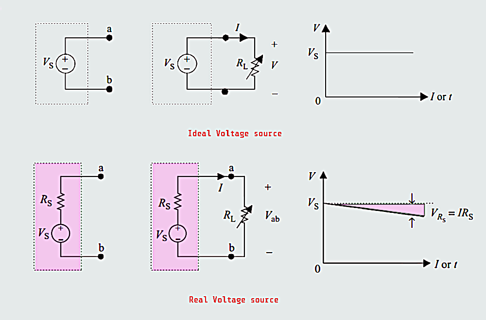
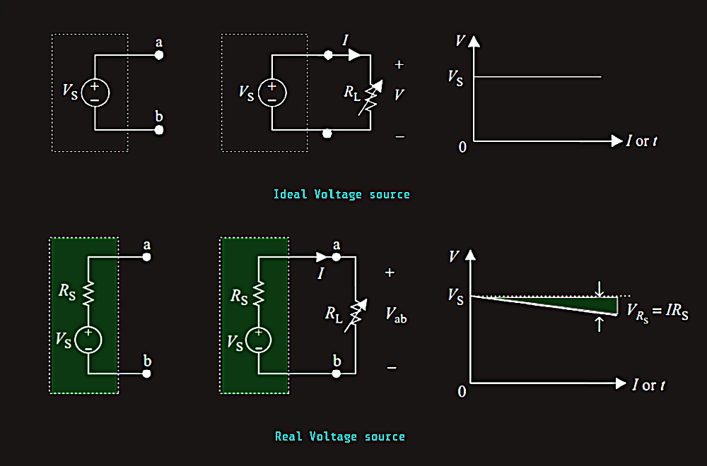
Ideal voltage source:
- It can provide a constant terminal voltage that is independent of the variations in its external circuit, Vab = Vs
- Its internal resistance, Rs = 0
- Its current depends on the variations in its external circuit
Real voltage source:
- It has a series internal resistance Rs, and Rs < RL
- The terminal voltage of the real voltage source is Vab = Vs - IRs
Industrial automation
Understanding PLC, HMI and SCADA
PLC Hardware and Wiring
Industrial automation has been in existence since before the programmable logic controller (PLC)
was developed in the late 1960s. Relays and timers were used for automating manufacturing processes
prior to the introduction of PLCs but they had so many challenges. Some of these challenges included
the large space occupied by relays and timers, the amount of time required to troubleshoot the system,
and making changes to the system was very difficult due to the fact that so many relays were hardwired
together in a specific order for the machine to operate. A PLC provides a solution to all these challenges
by needing less space, being easy to troubleshoot, and changes can easily be made to a control system
that uses a PLC.
A PLC is an industrial computer that consists of both hardware and software used for automating
industrial processes. They are mostly used in manufacturing industries and can be found in other
industries including transportation, manufacturing, warehousing, oil and gas, building, and so on.
A PLC can also be referred to as an electronic device that accepts inputs from sensors and switches,
processes them, and gives out signals to control actuators. PLCs take data from the plant floor through
switches and sensors, they then execute the program logic written into them and give an output signal
based on the result of the program logic to control actuators or machines connected to them.
The hardware part of a PLC consists of various modules. The basic modules that make up a PLC
include the following:
1. The Power Supply
2. The CPU
3. Input module
4. Output module
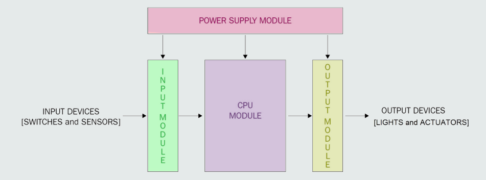
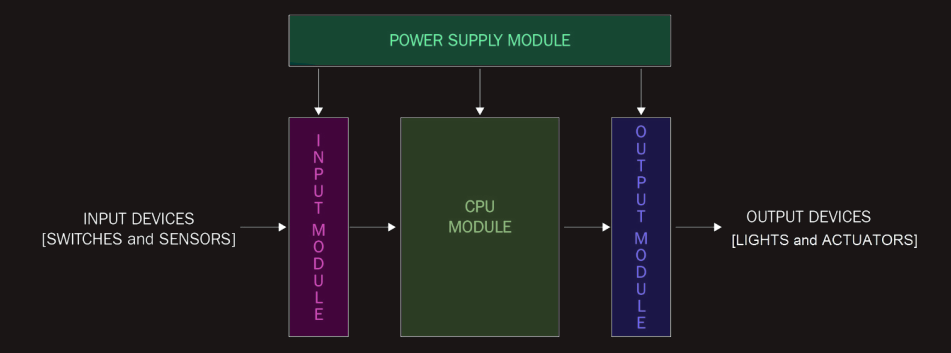
The power supply part of a PLC provides the appropriate voltage and current to other parts/modules of
the PLC. Most PLCs use 24V DC and the supply from the grid is usually 110V or 220V AC, depending
on the country. A power supply takes the 220V or 110V AC as input and provides the required voltage
(usually 24V DC) and current as output to other parts of a PLC. The current rating of power supplies
can range from 2 to about 50 amps, depending on the PLC size. The power supply module of a PLC provides the energy required for the PLC to function.
The power supply works by stepping down
the line voltage of usually 110V or 220V AC to a lower AC voltage with the aid of a transformer.
A rectifier then converts the lower voltage AC to DC. A capacitor smooths or filters the DC, and a
regulator circuit within the unit provides a regulated DC output of usually 24V DC.
The central processing unit (CPU) consists of
a processor, memory, and other integrated circuits that handle program execution, storage, and
communication to other external devices including a programming device or personal computer
(PC), a Human-Machine Interface (HMI), a variable frequency drive (VFD), and so on. The CPU
controls and coordinates the entire operation of the PLC. The CPU executes the program written into the PLC and
makes the decisions needed by the PLC to automate or operate machinery and communicate with
other devices.
The input module is the part that connects all the input devices (switches and sensors) to the PLC. It
allows the PLC to monitor the current state of switches and sensors that are required to perform the
necessary control functions when executing a program. Input modules can basically be classified as
digital and analog. Digital input modules are used when the input devices to be connected produce
a discrete signal (ON or OFF), while analog input modules are used when the input device to be
connected produces an analog signal (that is 0-5V, 0-10V, 0-20mA, or 4-20mA).
The input module receives signals from switches and sensors and sends them to the CPU for processing.
The output module is the part that connects the PLC to the output devices or actuators. An output device can be a
light, relay, contactor, solenoid valve, control valve, and so on. The PLC output module operates or
controls the output devices based on the state of the inputs and the result of the written program in
the CPU. Output modules can also be classified into two, namely digital output modules and analog
output modules. The digital output module can control output devices or loads that are either ON or
OFF. The digital output module produces binary outputs (1 or 0), which means ON or OFF for loads that
are either ON or OFF. Analog output modules, on the other hand, produce variable or changing
signals that can range from 0-5V, 0-10V, 0-20mA, or 4-20mA. They are used for controlling output
devices that require a control signal between full ON and full OFF.
The output module takes the processed signal from the CPU to control output devices.
Other PLC modules include Communication module and Positioning module - Communication module of a
PLC usually have an interface or communication port that supports a particular communication
or protocol (for example, PROFIBUS, PROFINET, DeviceNet, Modbus, AS-i or Ethernet). This allows the PLC to communicate with other PLCs, PCs, and
other devices within the factory facility or at a faraway distance. Positioning module allows various position control, speed control, torque control,
and so on to be carried out in a motion control system.