


Effects of frequency in a capacitive circuit
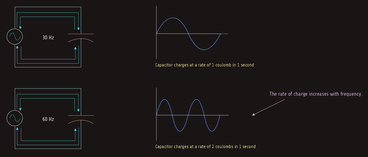
One of the factors that determine the capacitive reactance of a capacitor is the frequency. Capacitive reactance is inversely proportional to frequency. As the frequency increases, the capacitive reactance decreases.
Assume now that a capacitor is connected to a 30-hertz line, and 1 coulomb of charge flows each second. If the frequency is doubled to 60 Hertz, 1 coulomb of charge will flow in 0.5 second because the capacitor is being charged and discharged twice as fast. This means that in a period of 1 second, 2 coulombs of charge will flow. Since the capacitor is being charged and discharged at a faster rate, the opposition to current flow is decreased. 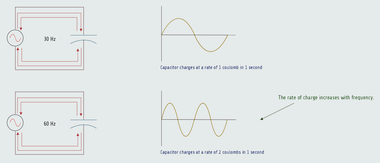
Resistive-Capacitive Series Circuits
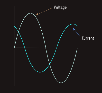
When a pure capacitive load is connected to an AC circuit, the voltage and current are 90° out of phase with each other. In a capacitive circuit, the current leads the voltage by 90 electric degrees.
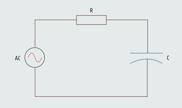
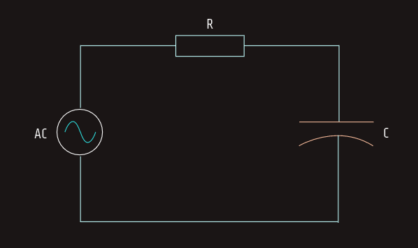
When a circuit containing both resistance and capacitance is connected to an AC circuit, the voltage and current will be out of phase with each other by some amount between 0° and 90°. The exact amount of phase angle difference is determined by the ratio of resistance to capacitance.
The procedure for solving circuit values is the same as in R-L series circuit explained earlier.
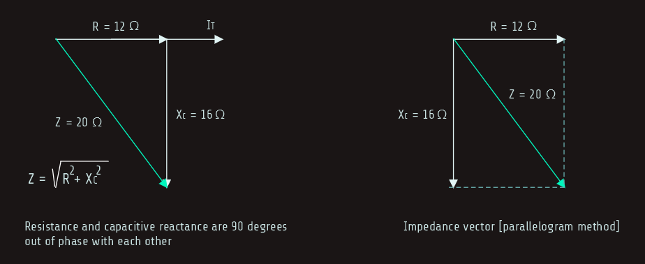
In the next example we have a series circuit containing 12 ohms of resistance and 16 ohms of capacitive reactance that is connected to a 240-volts, 60-hertz line. We need to calculate following values...
Impedance
The total impedance (Z) is the total current-limiting element in the circuit. It is a combination of both resistance and capacitive reactance. Since this is a series circuit, the current-limiting elements must be added. Resistance and capacitive reactance are 90° out of phase with each other, forming a right triangle with impedance being the hypotenuse. 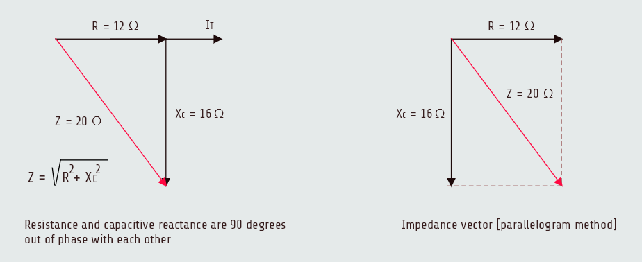
Total current
Now that the total impedance of the circuit is known, the total current flow (IT) can be computed:
IT = E/Z = 12 [A]
Voltage drop across the resistor
In a series circuit, the current is the same at any point in the circuit. Therefore, 12 amperes of current flow through both the resistor and the capacitor. The voltage drop across the resistor (ER) is:
ER = IxR = 144 [V]
True power
True power (P) for the circuit can be computed by using any of the watts formulas as long as values that apply only to the resistive part of the circuit are used. We already know that current and voltage must be in phase with each other for true power to be produced.
P = ERxI = 1728 [W]
Capacitance
We can found the amount of capacitance using formula:
C = 1/(2πfxC)
C = 165.8 [µF]
Voltage drop across the capacitor
The voltage drop across the capacitor (EC) can be computed using the formula:
EC = IxXC
EC = 192 [V]
Total voltage
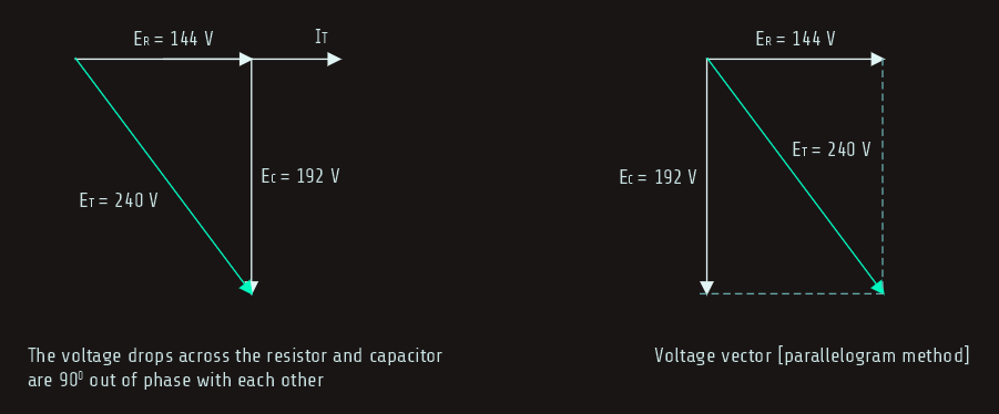
The amount of total voltage (ET) applied to the circuit in this example is given as 240 volt, but it is possible to compute the total voltage if it is not known by adding the voltage drop across the resistor and the voltage drop across the capacitor together. In a series circuit, the voltage drops across the resistor and capacitor are 90° out of phase with each other and vector addition must be used. These two voltage drops form the legs of a right triangle, and the total voltage forms the hypotenuse.
ET = √(ER2+EC2)
ET = 240 [V] 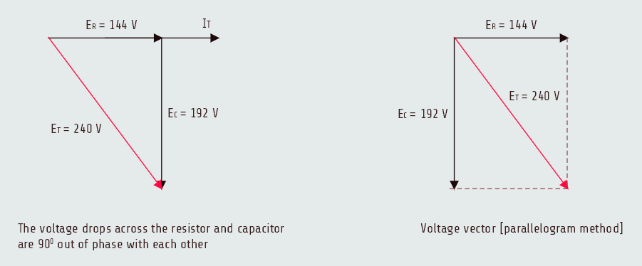
Reactive power
The reactive power (VARs) in the circuit can be computed in a manner similar to that used for watts except that reactive values of voltage and current are used instead of resistive values.
VARs = ECxI
VARs = 192[V] x 12[A]
VARs = 2304
Apparent power
The apparent power (VA) of the circuit can be computed in a manner similar to that used for watts or VARs, except that total values of voltage and current are used.
VA = ETxI
VA = 240[V] x 12[A]
VA = 2880
And also:
VA = √(P2+VARs2)
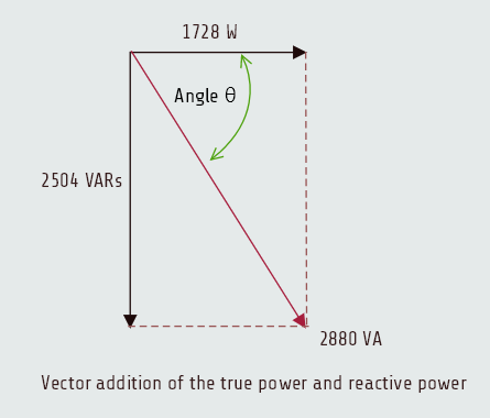
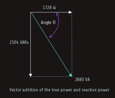
Angle Theta
The power factor of a circuit is the cosine of the phase angle. Since the power factor of this circuit is 0.6, angle theta (∠ θ ) is:
cos ∠ θ = PF
cos ∠ θ = 0,6
∠ θ = 53,130
The current leads the voltage by 53.130 in this circuit. 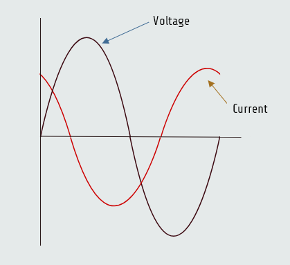
Power factor
Power factor (PF) is a ratio of the true power to the apparent power. It can be computed by dividing any resistive value by its like total value.
PF = P/VA
PF = 0,6 = 60 %