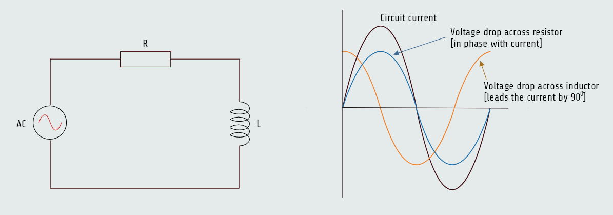
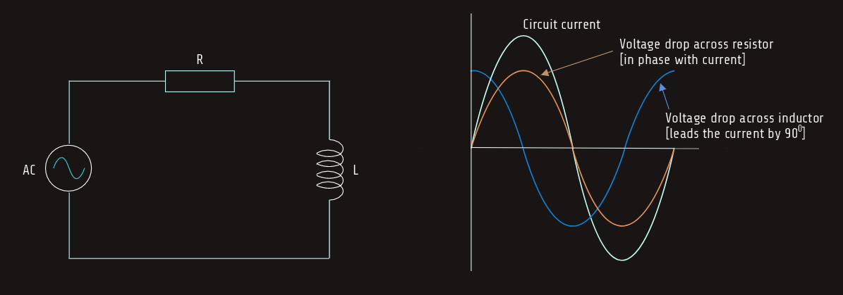
Voltage and current relationships in an inductive circuit
We have already learned that when current flows through a pure resistive circuit, the current and voltage are in phase with each other. In a pure inductive circuit, the current lags the voltage by 90°. How the current and applied voltage can become 90° out of phase with each other can best be explained by comparing the relationship of the current and induced voltage.
We know that the induced voltage is proportional to the rate of change of the current (speed of cutting action). 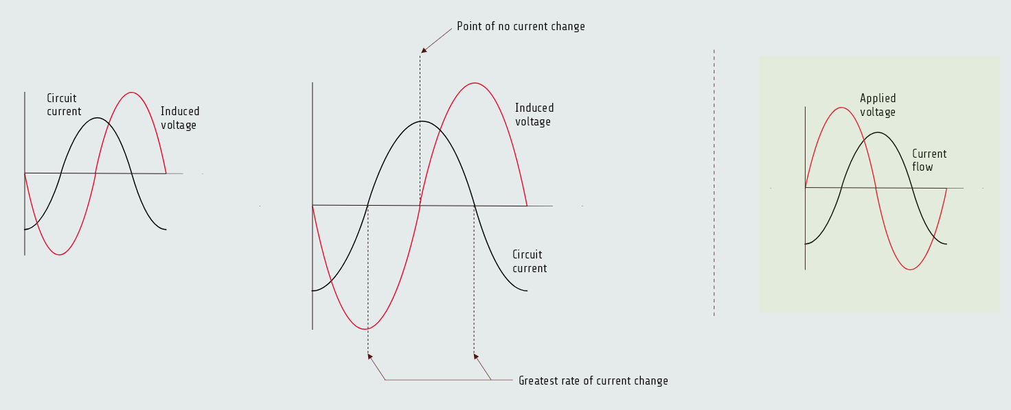
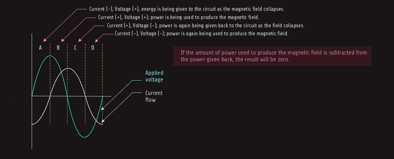
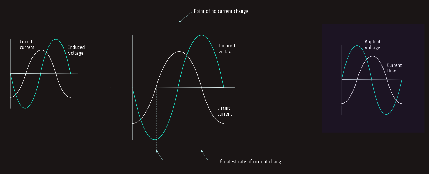 At the beginning of the waveform shown above, the current is at its maximum value in the negative direction. At this time, the current is not changing, so induced voltage is zero. As the current begins to decrease in value, the magnetic field produced by the flow of current decreases or collapses and begins to induce a voltage into the coil as it cuts through the conductors.
The greatest rate of current change occurs when the current passes from negative, through zero, and begins to increase in the positive direction. Since the current is changing at the greatest rate, the induced voltage is maximum.
As current approaches its peak value in the positive direction, the rate of change decreases, causing a decrease in the induced voltage. The induced voltage will again be zero when the current reaches its peak value and the magnetic field stops expanding.
It can be seen that the current flowing through the inductor is leading the induced voltage by 90°.
So, since the induced voltage is 180° out of phase with the applied voltage, the current lags the applied voltage by 90°, that is shown above on the right figure.
Power in an inductive circuit
We have seen that in a pure resistive circuit, the true power, or watts, is equal to the product of the voltage and current.
In a pure inductive circuit, however, no true power, or watts, is produced.
Voltage and current must both be either positive or negative before true power can be produced.
Since the voltage and current are 90° out of phase with each other in a pure inductive circuit, the current and voltage will be at different polarities 50% of the time and at the same polarity 50% of the time. During the period of time that the current and voltage have the same polarity, power is being given to the circuit in the form of creating a magnetic field. When the current and voltage are opposite in polarity, power is being given back to the circuit as the magnetic field collapses and induces a voltage back into the circuit. Since power is stored in the form of a magnetic field and then given back, no power is used by the inductor.
However, any power used in an inductor is caused by losses such as the resistance of the wire used to construct the inductor, generally referred to as I2R losses, eddy current losses, and hysteresis losses. 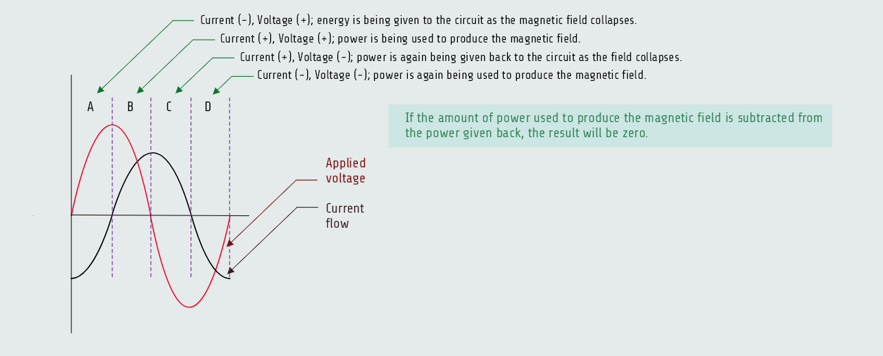
Reactive power
Although essentially no true power is being used, except by losses mentioned above, an electrical measurement called volt-amperes-reactive (VARs) is used to measure the reactive power in a pure inductive circuit. VARs can be computed in the same way as watts except that inductive values are substituted for resistive values in the formulas.
VARs = EL x IL
VARs = EL2/XL
VARs = IL2 x XL
• EL - voltage applied to an inductor
• IL - current flow through an inductor
• XL - inductive reactance
We have been generally assumed so far that an inductor has no resistance and that inductive reactance is the only current-limiting factor. In reality, that is not true. Since inductors are actually coils of wire, they all contain some amount of internal resistance. Inductors actually appear to be a coil connected in series with some amount of resistance. The amount of resistance compared with the inductive reactance determines the quality (Q) of the coil; higher the ratio of inductive reactance to resistance is considered to be inductors of higher quality (Q = XL/R). In a perfect world, an inductor would only have inductive reactance XL, which is its ability to oppose changes in alternating current (AC) using its magnetic field. It wouldn't waste any energy. But in the real world, inductors are made of wire, and wire has resistance R; resistance converts some of that electrical energy into useless heat.
An inductor constructed with a large wire will have a low wire resistance and, therefore, a higher Q, while inductors constructed with many turns of small wire have a much higher resistance and, therefore, a lower Q.
Although inductors have some amount of resistance, inductors that have a Q of 10 or greater are generally considered to be pure inductors. Once the ratio of inductive reactance becomes 10 times as great as resistance, the amount of resistance is considered negligible.
Let's say we have an inductor that has an inductive reactance of 100 ohm and a wire resistance of 10 ohm.
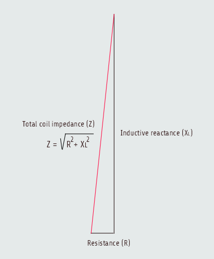
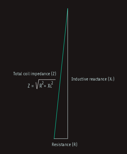
The inductive reactive component in the circuit is 90° out of phase with the resistive component.
This relationship produces a right triangle with the total current-limiting effect of the inductor as a combination of the inductive reactance and resistance. This total current-limiting effect is called impedance and is symbolized by the letter Z.
Z = √(R2+XL2)
Z = √(102+1002)
Z = √10.100
Z = 100,499 Ω
We can see that the value of total impedance for the inductor is only 0.5 ohm greater than the value of inductive reactance.
R-L series circuit
When a pure resistive load is connected to an AC circuit, the voltage and current are in phase with each other; when a pure inductive load is connected to an AC circuit, the voltage and current are 90° out of phase with each other. So, when a circuit containing both resistance R, and inductance L, is connected to an AC circuit, the voltage and current will be out of phase with each other by some amount between 0° and 90°.
The exact amount of phase angle difference is determined by the ratio of resistance as compared to inductance.
In the following example, a series circuit containing 30 ohms of resistance (R) and 40 ohms of inductive reactance (XL) is connected to a 240-volts, 60-hertz line. It is assumed that the inductor has negligible resistance. We will calculate different values during the following analysis.