


SCADA systems can automate the data acquisition process by recording values from instrumentation or electronic sensors in the field. This function can be executed by linking the software to a PLC where the values are read and written. Once a change in values is detected, information is passed into a database on the server and stored for retrieval at any time. Historically data was recorded manually by an operator, on software, or by paper. SCADA systems can run reports to track downtime and equipment efficiencies to increase productivity.
Functionalities of a SCADA system are:
- Supervision
- Control
- Data Acquisition
- Alarm and Events Management
- Trending
- Security
- Historian and Reports
- Web Connectivity
Most SCADA systems are compliant with the OPC (Object Linking and Embedding for Process Control) interoperability. With this feature built-in, a certain SCADA system is guaranteed to communicate with any controller brand. This gives any user the capability to select a SCADA that meets their commercial and technical requirement, whether of the same brand or not. In fact, SCADA applications come with their own OPC or communication management tool. The integration of a SCADA system with other hardware components such as RTUs, HMI devices, or DCS platforms needs to take place through either OPC drivers or proprietary communication management tools from each vendor.
Industrial automation
Industrial automation begins at the field Device Level.
These are few examples of field devices:
· Photoelectric digital sensors that detect a change in light intensity to sense objects within a field of view.
· Level analog sensors such as those with radar can detect the chemical level in a tank by emitting a frequency and measuring the return wave.
· Field devices also include industrial AC or DC motors that can vary in speed to accommodate different machine or process requirements.
· These motors can have Variable Speed Drives – VFDs that can modulate and control the speed of the motor.
The PLC is on the next tier, known as the control level of the pyramid. With this controller, we can execute functions based on inputs in the form of electrical signals translated in binary form of a 1 for on or 0 for off, with outputs such as a motor, pneumatic actuator, or any mechanical actuator. Human intervention is reduced nowadays when the PLC controls the equipment and can complete the tasks more precisely.
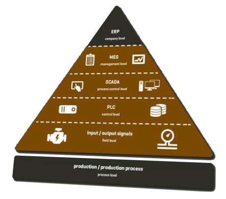
A Human Machine Interface (HMI) runs a computerized application at the “machine level” so that the operator can directly interface with the equipment without needing to edit any of the PLC code.
The automated industrial facility relies heavily on communication protocols to facilitate the interaction of various types of remote input or output devices. At the field Device Level, we have protocols such as IO-Link or Modbus RTU that give sensors and the PLC a means of communicating. The PLC acts as the master, assigns the sensor its parameters, and accesses its process values such as temperature, pressure, conductivity, and level. Modules transfer the data to the PLC using protocols such as EthernetIP or Profinet. EthernetIP has almost eliminated the need for field device wiring, reducing installation costs.
The last tier of the industrial automation hierarchy is the supervisory level, SCADA.
SCADA software is commonly installed on a server computer and is accessed by computers or clients within the same network. A user can access pre-configured and customizable screens that allow control of components on the ground floor, such as valves, motors, actuators, etc.
Guide to PLC
Programmable Logic Controllers (PLC) are defined as miniature industrial computers that contain hardware and software used to perform control functions. A PLC would be used for the automation of industrial electromechanical processes, such as control of machinery on factory assembly lines, food processing or power plant automation, and so on. They are designed for multiple arrangements of digital and analog inputs and outputs with extended temperature ranges, immunity to electrical noise, and resistance to vibration and impact. A PLC consists of two basic sections: the central processing unit (CPU) and the Input/Output (I/O) interface system. 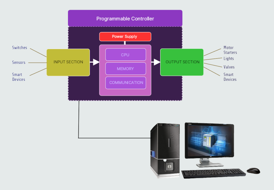
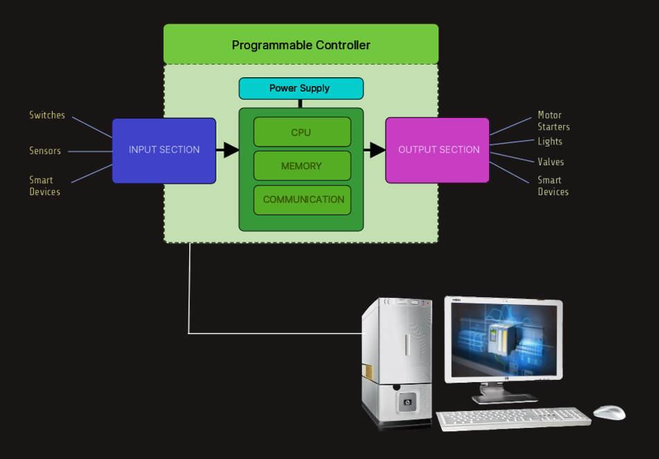 The CPU controls all system activity primarily through its processor and memory system. The CPU consists of a microprocessor, memory chip and other integrated circuits to control logic, monitoring and communications. In programming mode the CPU will accept changes to the downloaded logic from a PC. When the CPU is placed in run mode it will execute the program and operate the process. Input data from connected field devices (switches, sensors, etc.) is processed, and then the CPU executes or performs the control program that has been stored in its memory system. Since a PLC is a dedicated controller it will process this one program over and over again. The time it takes for one cycle through the program is called scan time and happens very quickly (1/1000th of a second, depending on program).
The input/output system is physically connected to field devices and provides the interface between the CPU and its information providers (inputs) and controllable devices (outputs). After the CPU processes the input data (input scan), it will then make any needed output changes after executing the user program (output scan).
There are four basic steps in the operation of all PLCs:
· Input Scan ---> Detects the state of all input devices that are connected to the PLC.
· Program Scan ---> Executes user created program logic.
· Output Scan ---> Energizes or de-energizes all output devices that are connected to the PLC.
· Housekeeping ---> Includes communicating with programming devices and performing internal diagnostics.
These four steps continually take place in a repeating loop.
Typical PLCs have a wide range of I/O modules available to accommodate all kinds of sensors and output devices. For example, discrete input modules can be used to detect object presence or events with devices such as proximity or photoelectric sensors, limit switches and pushbuttons. Discrete output modules can control “ON/OFF” loads such as motors, lights, and solenoid valves. Analog input modules can accept signals from process instrumentation such as flow, pressure, temperature and level transmitters. Analog outputs will command loads that require a varying control signal, such as panel meters, variable frequency drives or analog flow valves.
Choosing the right controller
Choosing the most effective controller for our application depends on a number of factors:
- Certain controller products may not be compatible with others. Making sure our existing products are compatible with any new products will save our time and money, if we're upgrading the system; or for building the system from scratch, we should check the appropriate entry.
- Certain environments may affect the operation of a controller. For example, typical controllers have an operating temperature of 0-55 degrees Celsius. If our application will include any extreme environmental conditions, or we have specific codes at our facility that must be met, we will need to either research products that meet those specifications or design the installation to meet requirements.
- The number and type of devices our system will include is directly linked to the amount of I/O that will be necessary for our system. We will need to choose a controller that supports our I/O count requirements and has modules that support our signal types.
a) We should determine how many discrete devices our system will have. Which types (AC, DC, etc.) are needed.
b) We should determine how many analog devices our system will have. Which types (voltage, current, temperature, etc.) are needed. - Specialty functions are not necessarily available in a controller CPU or in standard I/O modules. Understanding the special functions our system may perform will help us determine whether or not we will need to purchase additional specialty modules; if the application will need high-speed counting or positioning, what about a real-time clock or other specialty feature...
- We should determine the type of CPU we will need: how much memory will our system require? How many devices will our system have (which determines data memory)? How large is our program, and what types of instructions will our program include (which determines program memory)? How fast a scan time we will need, etc.
- If subsystems will be needed at long distances from the CPU, we will need a controller that supports remote I/O and not (only) local I/O. We will also have to determine if the remote distances and speeds supported will be adequate for our application. Serial and Ethernet-based I/O hardware are two typical choices available for most systems. This I/O may also be referred to as distributed I/O, and may require a particular protocol, such as Modbus.
- Communication ports (other than the programming port) are not always included with a controller. Knowing our system communication requirements will help us choose a CPU that supports our communication requirements, or additional communication modules if necessary.
- Certain controllers may not support every type of instruction. We will need to choose a model that supports all instructions that we may need for a specific application. For example, built-in PID functions are much easier to use than writing our own code to perform closed-loop process control. Typical instructions such as timers, counters, etc. are available in most controllers; we should note any other special instructions required here.
Choosing the most effective PLC for our application takes some careful thought and research in order to save money and prevent problems in the long run.