


The Logic Gate Level
On this level within an integrated circuit, signals are being converted, or combined, to turn into other signals. In digital electronics, signals are expressed in binary numbers where ground voltage is represented by a ‘0’ and positive voltage is represented by a ‘1’. By feeding these binary signals into tiny units called logic gates, they get processed in different ways depending on the type of logic gate.
Logic gates are very small building blocks of a digital system. They perform logical operations on one or more input signals and they produce a single output.
In digital processors, all operations are done by complex internal units that are created by combinations of logic gates. 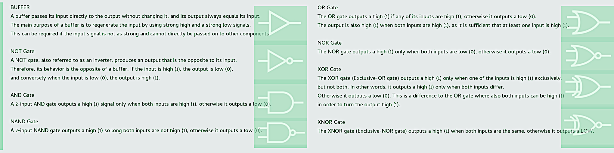
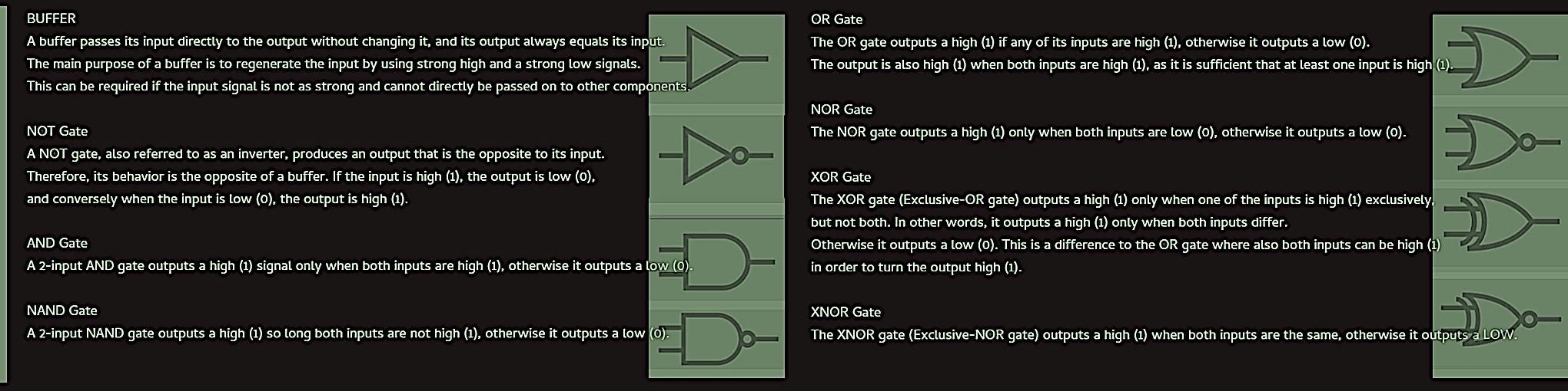 Some of the gate symbols have little circles attached. These circles always indicate a logical negation. Also, power connections are not shown. Gate symbols always only include input and output connections.
The functionality of logic gates is realized by certain arrangements of electrical components within an integrated circuit. Nearly all of today’s digital integrated circuits use transistors for the creation of logic gates, but there have been numerous other approaches in the past, using transistors, resistors or even diodes to design circuits that function as logic gates. These different designs of electronic circuits are called logic families, that include: RTL (Resistor Transistor Logic), ECL (Emitter Coupled Logic), DTL (Diode-Transistor Logic), PMOS and NMOS logic families, TTL (Transistor-Transistor Logic), IIL (Integrated Injection Logic) and CMOS (Complementary Metal Oxide Semiconductor).
The Register Transfer Level
The register transfer level focuses on digital circuits and flows of binary signals (data) between registers, and the logical operations performed on those signals. Registers are functional units that contain some fast storage; therefore, the register transfer level primarily consists of functional units that either store data, or process them in a certain way, and communication channels that interconnect these functional units.
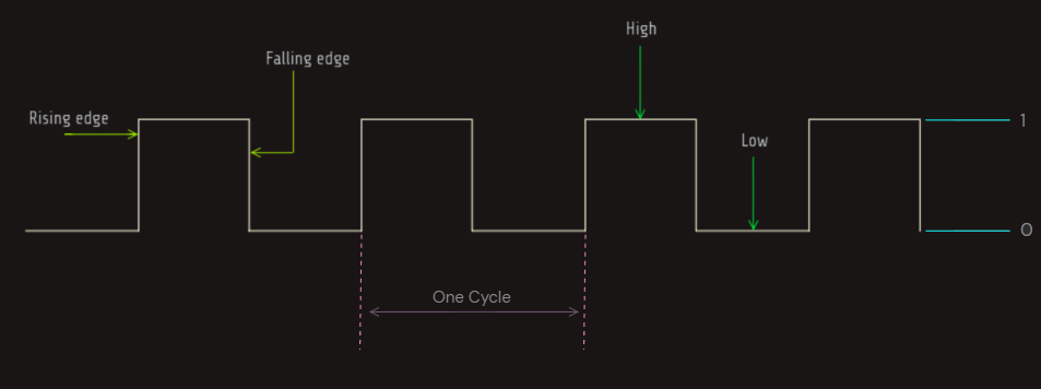
In digital integrated circuits, numerous functional units perform logical operations at the same time. In cases where functional units rely on input signals from previous components, they can only start processing when these previous components have completely finished their logic operations. As a subsequent functional unit has no information on the processing status of its previous components, almost all functional units must be synchronized by reliable external impulses. These external impulses are provided by a clock signal that oscillates between a high (1) and a low (0) voltage. A typical clock signal uses a square wave with a constant frequency. The clock signal is supplied to those functional units that require synchronization. Depending on the design of those units, these can become active at the rising edge of the clock signal, at the falling edge of the clock cycle, or during the intervals where the clock signal is high or low. 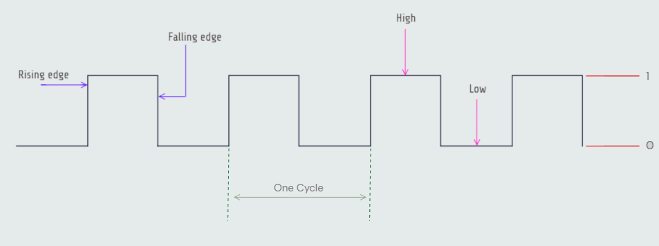
 The cycle time is chosen so that the slowest functional unit still has enough time to complete its operation. In today’s computer processors, cycle times are within the range of nanoseconds (billionth of a second). The clock frequency (also referred to as clock rate or clock speed) is the number of cycles the clock performs in one second. Therefore, in order to get the frequency, one second must be divided by the cycle time. With a cycle time of one nanosecond, the correspondent clock frequency is one gigahertz (GHz). Clock signals are produced by clock generator circuits. These usually rely on a crystal resonator that is combined with an amplifier circuit. Most integrated circuits require an external clock generator to provide the clock signal.
Any functional unit consists of logic networks that are implemented from logic gates. A distinction is made between combinational logic functions and sequential logic functions.
In a combinational circuit, the output is only determined by the logical function of their present input states (logic 0 or logic 1). As soon as the input change, all information about the previous inputs is lost, and the output is recalculated. For that reason, combinational logic circuits have no memory. Combinational circuits are also known as time-independent and stateless circuits.
In a sequential circuit, the output is dependent on both the present input states and the previous output state. For that reason, sequential Logic circuits have some form of memory built in. This is achieved by a feedback loop that connects the output back to the input.
Combinational Functional Units are: Multiplexers, Demultiplexers, Encoders, Decoders, Arithmetic Logic Units; Sequential Functional Units are: Latches, Flip-Flops, Registers.
Multiplexers and Demultiplexers
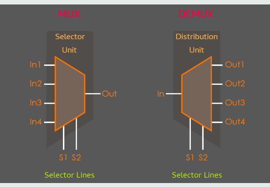
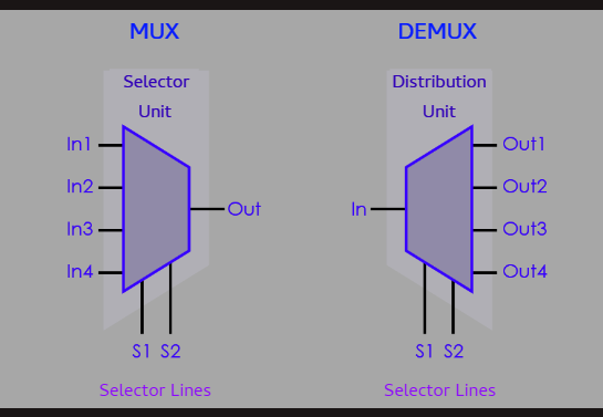
A multiplexer (MUX) is a circuit that accepts multiple data inputs and has one single output. The circuit itself serves as a selector that establishes a connection between one of the inputs and the output depending on the signals provided by the selector lines. Therefore, a multiplexer performs a parallel to serial conversion. A demultiplexer (DEMUX), on the other hand, is a circuit that has one single input and multiple outputs. The circuit is a distributor that establishes a connection between the input and one of the outputs depending on the signals provided by the selector lines. Therefore, a demultiplexer performs a serial to parallel conversion. Demultiplexers are literally reversed multiplexers, and therefore the same applies for their numbers of selector lines and outputs.
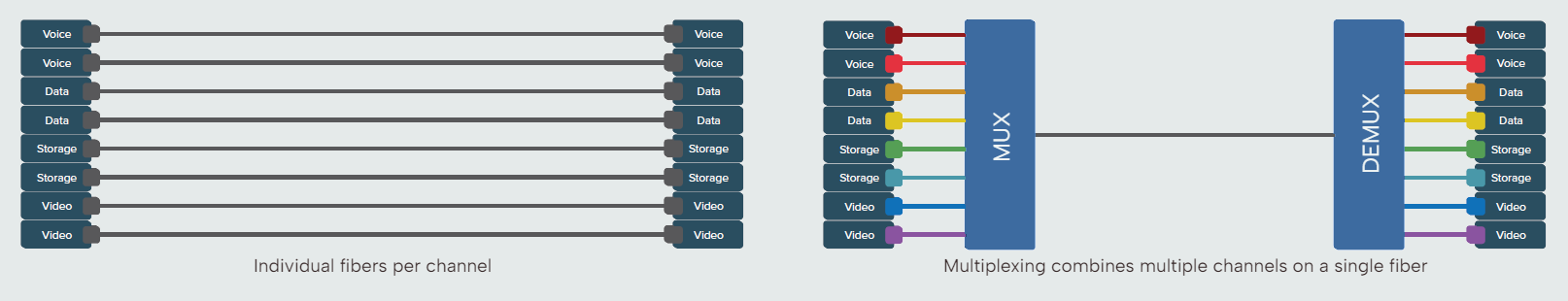
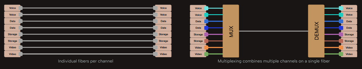
Multiplexers and demultiplexers are often used in communication systems to carry multiple data signals using a single line for transmission. Implementing a single transmission line is reducing cost if larger distances need to be overcome. In digital integrated circuits, multiplexers are often used as input selectors to control which data line is connected to an input of a specific unit.
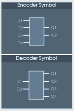
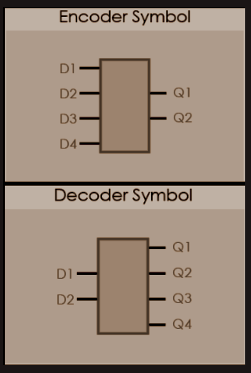
Encoders and Decoders
An encoder performs a conversion of an input with two to the power of n lines into an n-bit binary code at the output. On the opposite, a decoder performs a conversion of an n-bit binary code into two to the power of n unique outputs.
Encoders are very useful circuits for various reasons. Encoding can be used to minimize the number of data lines required for signal transmission. A particularly useful application for encoding is the translation of input devices into binary code. For instance, pocket calculators use encoders to translate the decimal numbers of their keypad into binary numbers so that they can be used for further operations. Also, computer keyboards use encoders to convert their alphanumeric keys into binary code that can be processed by the computer.
Decoders have a number of useful applications. Their one-hot output signals can serve as enable signals for functional units (instruction decoding). In memory circuits they can also be used to enable different banks of memory, so in this application the inputs of decoders effectively become address lines. When a continuous counter is connected to their input lines, decoders can also be used as sequencers to turn various devices off or on in a repetitive and sequential way.
Arithmetic Logic Unit (ALU)
An arithmetic logic unit (ALU) is a functional unit that performs arithmetic (addition, subtraction, etc.) and logical (AND, OR, etc.) operations on integer binary numbers. It is also one of the most fundamental units of many computing circuits, including the central processing unit (CPU) of computers, and the graphic processing unit (GPU) of video cards. Individual ALUs can be highly specialized to certain logic operations, and an integrated circuit may include multiple ALUs.
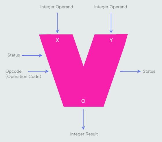
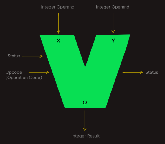
Inputs of an ALU are primarily the operands which are the data to be operated on. In addition, an ALU has opcodes (operation codes) as inputs to control the type of operation the ALU shall perform (modern ALUs feature more than 100 instruction opcodes). A separate status input typically contains information about a previous operation. The output of an ALU is the result of the performed operation. In many designs, the ALU also has a status output that is either forwarded to other components of the ALU for further processing, or used as a status flag that indicates different conditions of an operation.