


Primary and secondary cells
Galvanic cells are classified as ‘primary cells’ and ‘secondary cells’, where:
• primary cells are those in which their electrochemical reaction is irreversible; they cannot be re-energized and, so, are disposable.
• secondary cells are those in which their electrochemical reaction is reversible; they can be fully re-energized and, so, are re-useable.
While primary cells are ‘galvanic cells’, secondary cells behave as ‘galvanic cells’ when they are being de-energized, but as ‘electrolytic cells’ when they are being re-energized.
Secondary cells (formerly called ‘accumulators’) are generally more economical than primary cells, despite their initially higher cost together with the cost of a recharging unit (i.e. ‘reenergizing unit’), but that cost can be spread out over numerous discharge/recharge cycles before they finally fail. This makes secondary cells ideal for portable tools, video camcorders, etc. While all cells ‘self de-energize’ to some degree, when they are not in use, this is significantly lower with primary cells than it is with most secondary cells, meaning that primary cells usually have a very much longer shelf life than energized secondary cells. This makes disposable primary cells the better choice for applications in occasional usage – such as in torches (flashlights).
There are numerous different types of cell within each of these two general classifications, and some of the more common are:
(1) primary cells - zinc-carbon, alkaline, miniature (mercury, silver, etc.)
(2) secondary cells - lead-acid, nickel-cadmium, lithium-ion
Anode and cathode
Free electrons always travel through the external circuit from a cell’s anode to its cathode.
So the terms ‘anode’ and ‘cathode’ are based on the direction of electron flow, and not on the polarity of the electrodes!
In other words, a cell’s ‘anode’ and ‘cathode’ change, according to whether a cell is de-energizing or is being energized – as shown in figure below. For a galvanic cell (a de-energizing cell), the negative plate is the anode and the positive plate is the cathode whereas, for an electrolytic cell (an energizing cell – i.e. with the current flowing in the opposite direction), the positive plate becomes the anode and the negative plate becomes the cathode.
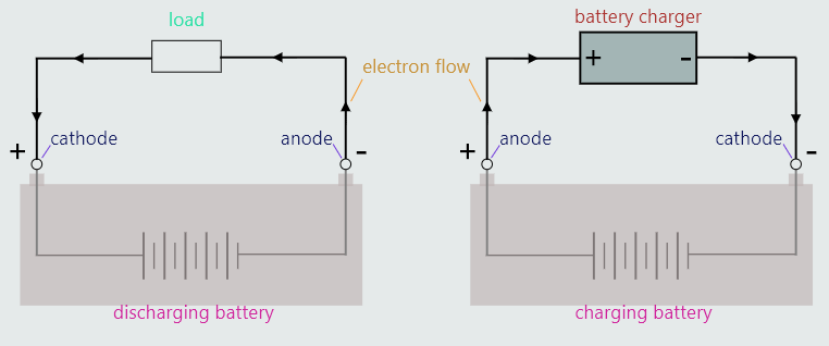
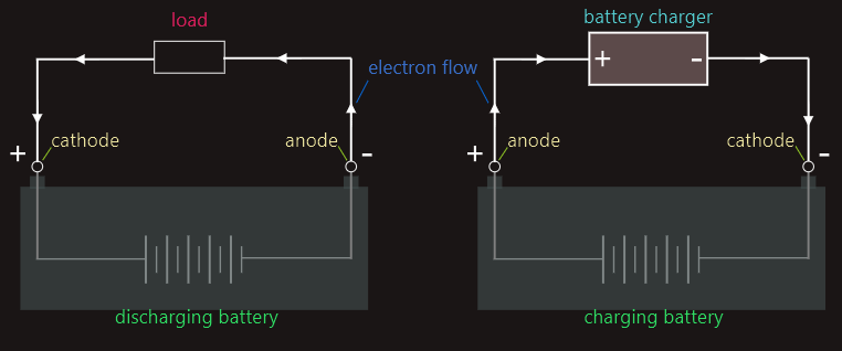
In most older literature we could find the definition of the ‘cathode’ as being the negative plate and the ‘anode’ as the positive plate. This is no longer the case!
To avoid confusion in using these terms, it is best referring to the electrodes as being either ‘negative’ or ‘positive’ plates.
Capacity and discharge rate
The capacity of a cell is a measure of its ability to deliver current to a load. Capacity is related to the quantity of active material the cell contains, the surface area of its plates, and its temperature.
The capacity of any particular cell is determined experimentally by the manufacturer, by de-energizing the cell at a constant current without exceeding a safe temperature, until the cell reaches its ‘cut-off’ voltage (i.e. the cell’s minimum voltage, below which the cell is considered to be fully de-energized) and, then, multiplying that current by the time taken to reach that cut-off voltage. A cell’s capacity, therefore, is the product of current and time and, so, is expressed in ampere hours (Ah). The capacity of smaller cells is expressed in milliampere hours (mAh).
A cell’s capacity is dependent upon the temperature at which that cell is operating, and capacity is normally expressed at a temperature of 25°C.
From the above explanation of capacity, it would seem that a lead-acid car battery, for example, with a capacity of, say, 200 Ah, is theoretically capable of delivering any combination of current and time, whose product is 200 Ah:
(1) 1 A for a period of 200 h
(2) 2 A for a period of 100 h
(3) 10 A for a period of 20 h
(4) 20 A for a period of 10 h
(5) 2000 A for a period of 6 min ...
In practice, we have to take care; excessively high currents cause excessively high temperatures which can actually melt a battery’s electrodes or even cause a battery to explode! And 2000 A is most certainly an excessively high current!
So, how do we know what the maximum ‘safe’ continuous de-energizing current should be for a particular cell or battery?
The answer is that we must refer to another part of a battery’s specification: its discharge rate (or, more accurately, ‘de-energizing rate’), expressed in hours. We can use this figure, together with the corresponding capacity, to determine a cell or battery’s maximum, safe, continuous de-energizing current – that is, the maximum continuous current that can be supplied to a load without overheating the battery.
A cell’s ‘discharge rate’ determines the maximum value of continuous current that cell is capable of supplying to its load without overheating.
For lead-acid cells, discharge rates are typically expressed as ‘8 h’, ‘10 h’ or as ‘20 h’. Often, the discharge rate is shown on specification sheets in the form: ‘C/8’, ‘C/10’ or ‘C/20’, where ‘C’ represents the capacity of the cell.
For example, the motor vehicle’s lead-acid battery that we described earlier may be quoted as having a capacity/discharge rate of ‘200/10’, which represents a capacity of 200 Ah at a discharge rate of 10 h, which means that it is designed to supply a maximum continuous de-energizing current of 20 A (i.e. 200 ÷ 10) for 10 h before the cell reaches its cut-off voltage.
An alternative way of defining a cell’s ‘capacity’ (mainly used with larger cells or batteries) is by expressing it in watt hours (Wh) which is actually a measure of the energy, not of the charge, a cell can supply. So, we need to convert Ah into Wh, that is:
energy [Wh] = capacity [Ah] x cell voltage [V]
Batteries
A battery is simply a number of cells connected together, which can be in series, parallel or series-parallel, also. It is not recommended that we connect different types of cell together, or to mix partially de-energized cells with fully energized cells. So let's assume that each cell is of the same type and has the same level of energy.
Cells are connected in series when the positive terminal of one cell is connected to the negative terminal of the next.
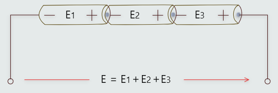
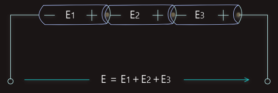
We connect cells in series when we want to increase the available e.m.f. The total e.m.f. of cells connected in series is the sum of their individual e.m.f.s.
The total internal resistance of cells connected in series is the sum of their individual internal resistances, like resistors in series, Rtotal=R1+R2+R3.
The total discharge current available from cells connected in series must not exceed the discharge current delivered by an individual cell.
Cells are connected in parallel when all their positive terminals are connected together and all their negative terminals are connected together.
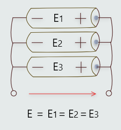
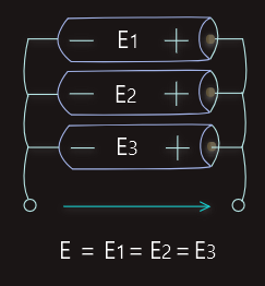
We connect cells in parallel when we want to maintain the same e.m.f. as a single cell, but wish to increase the available discharge current.
The total internal resistance of cells connected in parallel is determined the same way like resistor in parallel, 1/Rtotal=1/R1+1/R2+1/R3.
The maximum discharge current available from cells connected in parallel is the sum of the currents deliverable by each cell.
If we want to increase both the terminal e.m.f. and the amount of discharge current deliverably, then we could use combination and connect cells in series-parallel.
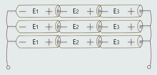
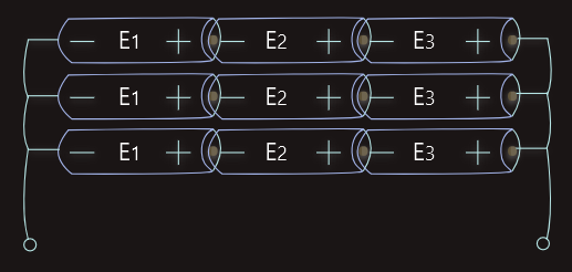
The total e.m.f. will be three times the e.m.f. of an individual cell, and the complete battery will be capable of delivering a discharge current that is three times that of any individual branch cell (which is that of any individual cell).
The total internal resistance can be determined in the same way as the total resistance of any series-parallel resistive circuit. In this case, the total internal resistance will be one-third of the internal resistance of one branch.
Batteries of different voltages should never be connected in parallel. The batteries could be damaged or one of the batteries could explode.
Common household battery voltages and current capabilities are shown on the next table.
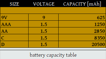
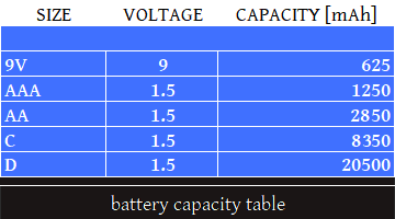
They all, except 9V, operate at the same voltage level (1.5V), but the difference is in current capacity. So, if it wasn't for the physical limitations, we could easily use all batteries for the same purpose and still have overall voltage level in the device. But the amount of current that the batteries could produce would be changed and as a result, the device may not have enough power to operate properly.
Current Conventions
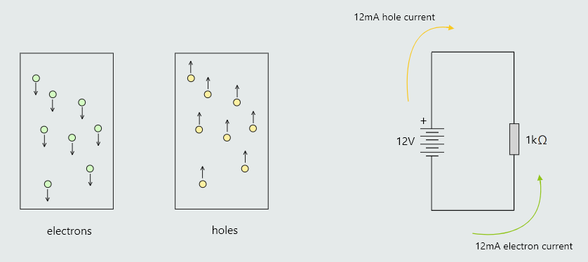
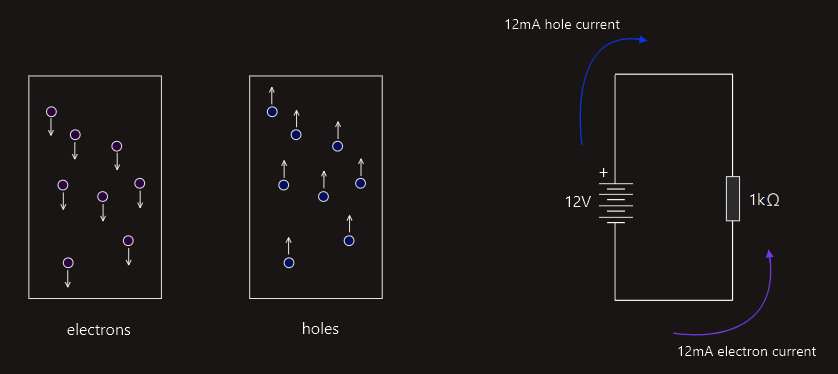
As electrons move in one direction, the holes they leave behind can be viewed as moving in the opposite direction.
Common electrical convention is to use hole current as the positive direction when discussing current flow. The reason for the convention of referring to hole current as the positive flow direction is to match current flow with the direction from higher to lower voltage.
Since water flows from a higher pressure to a lower pressure, a natural analogy is to have current flow from a higher voltage to a lower voltage.