


The time necessary for current in an inductor to reach its full Ohm’s law value - RL time constant is given by formula:
τ=L/R
• τ - time for one time constant (sec.)
• R - resistance (ohms)
• L - inductance (henrys)
Motor principle
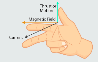
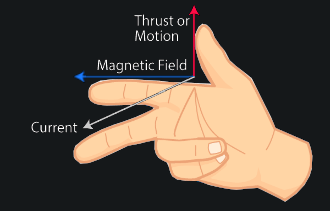
Fleming's Hand Rules
Whenever we use conventional current flow, Fleming’s Left-Hand Rule is used for ‘motor action’, while Fleming’s Right-Hand Rule is used for ‘generator action’. Depending on whether such a machine functions as a generator or a motor, the moving part that is attached to a mechanical system receives mechanical input or provides mechanical output. Each of these two above rules relates the relationships between the direction of a magnetic field, the direction of motion of a conductor within that field and the conventional direction of the current (and corresponding voltage).
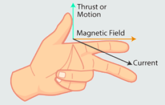
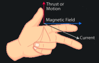
1. When a current-carrying conductor is placed in a magnetic field, the conductor is subject to a force that acts to move the conductor out of the field. The direction of the magnetic field (north to south) is represented by the first finger. The direction of the conventional current is represented by the second finger. The direction of the motion, caused by the resulting force, is then represented by the thumb.
2. When a conductor is moved through a magnetic field, a voltage is induced into the conductor. If this conductor forms part of a closed loop, then a current will flow in the same direction as the induced voltage. The direction of the magnetic field (north to south) is represented by the first finger. The direction of the motion of the conductor through the field is then represented by the thumb. The direction of the induced e.m.f. (and any resulting current) is represented by the second finger.
Motor action
We learnt earlier that a current-carrying conductor placed between the poles of a magnet will experience a force at right-angles to the field’s magnetic flux. This force, which is known as the ‘Lorentz Force’, acts to push the conductor out of the magnetic field.
F=BIl
· F - force [N]
· B - flux density [N]
· I - current [A]
· l - length of conductor in field [m]
Last equation only applies to the condition when the conductor is perpendicular to the main flux.
If it lies at some angle less than 90°, then the force exerted on it will be reduced, so in general: F=BIlsinθ [N]
The principle of a force exerted on a current carrying conductor forms the basis of operation of a linear motor. However, since most electric motors are rotating machines, the above system must be modified.
Let us consider the conductor formed into the shape of a rectangular loop, placed between two poles, and current passed through it. A cross-sectional view of this arrangement, together with the flux patterns produced is shown on the next figure.
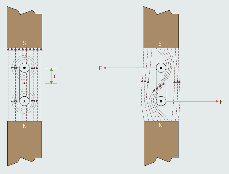
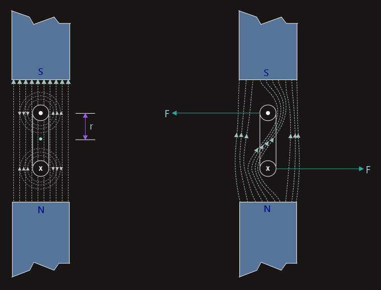
The flux patterns for the two sides of the loop will be in opposite directions because of the direction of current flow through it. The result is that the main flux from the poles is twisted as shown on the second figure. This produces forces on the two sides of the loop in opposite directions. Thus there will be a turning moment exerted on the loop, in a counterclockwise direction.
So the torque exerted on each side of the loop is given by T=Fr [Nm].
F=BIlsinθ [N], sinθ=1
The total torque exerted on the loop will be:
T=2BIlr [Nm]
It would have been seen that a single-turn loop produces a very small amount of torque, even if the coil dimensions and current were increased by some factor in specific cases. Using multi-turn coil can solve this problem in practice. Then, for N turns we would have the total torque T=2NBIlr [Nm].
The term 2lr in the above expression is equal to the area ‘enclosed’ by the coil dimensions, so this is the effective csa A, of the field affecting the coil.
T=BANI [Nm]
The principle of using a multi-turn current-carrying coil in a magnetic field is therefore used for rotary electric motors. The same principles apply to the operation of analogue instruments known as moving coil meters.
Generator action
The English physicist Michael Faraday (1791–1867) showed that the opposite of ‘motor action’ also occurs. That is, moving a conductor through a magnetic field (or moving the magnetic field relative to the conductor) will induce a voltage into the conductor. The direction in which this voltage acts can be determined by applying Fleming’s Right-Hand Rule. If the conductor forms part of a closed circuit, then this induced voltage will cause a current to flow in the same direction. The magnitude of this induced voltage, when the conductor is moved perpendicularly through a magnetic field, is given by the following equation:
U=Blv
· U - induced voltage [V]
· B - flux density [N]
· l - length of conductor in field [m]
· v - velocity of conductor [m/s]
Comparing ‘generator action’ with ‘motor action’, we will notice that the voltage (U) induced into the conductor by ‘generator action’ acts in the opposite direction to the voltage (E) that drives the current that causes ‘motor action’. For this reason, we call the voltage induced into the conductor by generator action a ‘back-e.m.f.’.
So, whenever there is ‘motor action’, there is always ‘generator action’ too, and the generated voltage (the back-e.m.f.) always opposes the voltage that causes the motor action to take place in the first place.
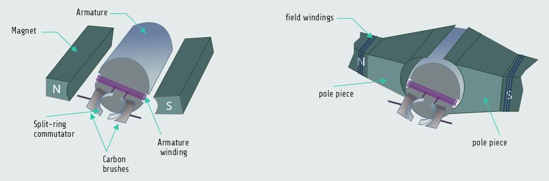
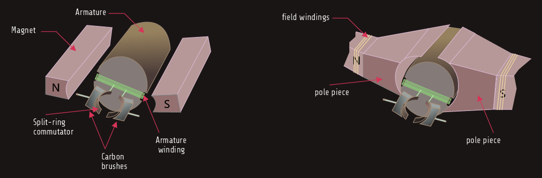
The stator comprises all the stationary components of the motor, including: the yoke (the cylindrical housing), the pole pieces and their field windings, bearings and the brushes.
The rotor comprises all the rotating parts of the motor, including: the drive shaft, armature, armature windings, commutator and impeller fan.
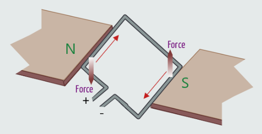
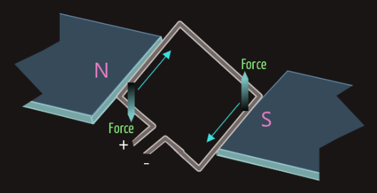
A single loop of conductor is placed between the poles of a permanent magnet, and is pivoted at its near and far ends in such a way that it is free to rotate.
With the current flowing around the loop in the direction shown, if we apply Fleming’s Left-Hand Rule to the left-hand side of the loop, we would find that it is subject to a downward-acting force; and applying the same rule to the right-hand side of the loop would confirm that it is subject to an upward-acting force. These forces couple to create a rotating force, or torque, which will act to rotate the loop in a counterclockwise direction.
The total torque acting on this single loop will be twice the torque acting on either side of the loop: T=2BIlr [Nm].
· r - perpendicular distance from centre of rotation (radius of the loop)
At the same time, a back-e.m.f. will be induced into the loop, the value of which will be: E=2Bl(ω·r)
A single-loop motor will produce very little torque so, in practice, a coil, called an armature winding, is used instead. If the armature winding has z loops, then the torque (and corresponding back-e.m.f.) will be increased by z.
So, whenever the armature winding is rotating, it behaves both as a motor and as a generator simultaneously! Passing a current through the winding causes it to move through the magnetic field (‘motor action’), but the movement of that winding through the field causes it to generate a voltage (‘generator action’) which always opposes the applied voltage that produces the current in the first place!
Ia=(E-U)/Ra
· Ia - current in loop [A]
· E - supply voltage [V]
· U - back e.m.f. [V]
· Ra - resistance of armature loop [Ω]
The ‘action’ and ‘reaction’ effect, described above, plays a very important role in causing d.c. machines (both motors and generators) to automatically react to changes in load.
For example, in the case of a d.c. motor, if its mechanical load should increase, then the armature winding will tend to slow down. As it slows down, the back-e.m.f. decreases, allowing the current through the armature winding to increase, creating more torque to match the increasing mechanical load. Similarly, if the motor’s mechanical load should decrease, then the armature winding’s speed will increase. As its speed increases, its back-e.m.f. also increases, reducing the load current and reducing the torque to match the reduced load.