


We have shown earlier capacitors connected in parallel, in series and made analysis of capacitive charge and discharge rates which is exponential. We have also seen what RC time constant is and how it can be calculated...
Capacitors are among the most used of electric components. They are used for power factor correction in industrial applications, in the start windings of many single-phase AC motors, to produce phase shifts for SCR and Triac circuits, to filter pulsating DC, and in RC timing circuits. Capacitors are used extensively in electronic circuits for control of frequency and pulse generation.
Capacitors can be divided into two basic groups:
· nonpolarized
· polarized
Nonpolarized capacitors are often referred to as AC capacitors because they are not sensitive to polarity connection. Nonpolarized capacitors can be connected to either DC or AC circuits without harm to the capacitor.
Polarized capacitors are generally referred to as electrolytic capacitors. These capacitors are sensitive to the polarity they are connected to and have one terminal identified as positive or negative. Polarized capacitors can be used in DC circuits only. If their polarity connection is reversed, the capacitor can be damaged and will sometimes explode. The advantage of electrolytic capacitors is that they can have very high capacitance in a small case.
Capacitance in AC Circuits
When a capacitor is connected to an AC circuit, current appears to flow through the capacitor. The reason is that in an AC circuit, the current continually changes direction and polarity.
Let us consider the hydraulic circuit where two tanks are connected to a common pump. Assume Tank A to be full and Tank B to be empty. Now assume that the pump pumps water from Tank A to Tank B. When Tank B becomes full, the pump reverses and pumps the water from Tank B back into Tank A. Each time a tank becomes filled, the pump reverses and pumps water back into the other tank. We can notice that water is continually flowing in this circuit but there is no direct connection between the two tanks. 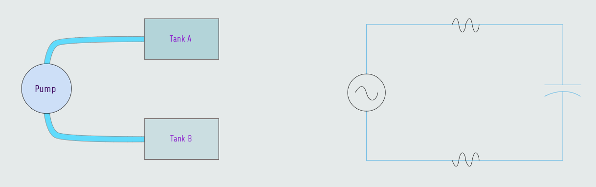
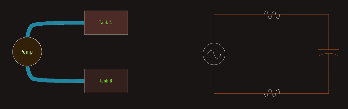 A similar action takes place when a capacitor is connected to an AC circuit. In this circuit, the AC generator or alternator charges one plate of the capacitor positive and the other plate negative. During the next half cycle, the voltage changes polarity and the capacitor discharges and recharges to the opposite polarity also. As long as the voltage continues to increase, decrease, and change polarity, current flows from one plate of the capacitor to the other. If an ammeter were placed in the circuit, it would indicate a continuous flow of current, giving the appearance that current is flowing through the capacitor.
Capacitive reactance
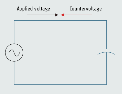
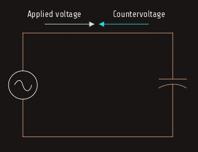
As the capacitor is charged, an impressed voltage is developed across its plates as an electrostatic charge is built up. The impressed voltage is the voltage provided by the electrostatic charge. This impressed voltage opposes the applied voltage and limits the flow of current in the circuit. This countervoltage is similar to the countervoltage produced by an inductor. The countervoltage developed by the capacitor is called reactance also. Since this countervoltage is caused by capacitance, it is called capacitive reactance (XC).
XC = 1/2πfC
· XC - capacitive reactance
· π - 3,1416
· f - frequency in hertz
· C - capacitance in farads
Pure capacitive circuit
It was shown before that the current in a pure resistive circuit is in phase with the applied voltage and that current in a pure inductive circuit lags the applied voltage by 90°. Here, we will see that in a pure capacitive circuit the current will lead the applied voltage by 90°.
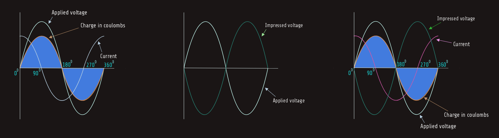
When a capacitor is connected to an AC, the capacitor charges and discharges at the same rate and time as the applied voltage. The charge in coulombs is equal to the capacitance of the capacitor times the applied voltage (Q = CxV). When the applied voltage is zero, the charge in coulombs and impressed voltage is also zero. When the applied voltage reaches its maximum value, positive or negative, the charge in coulombs and impressed voltage also reaches maximum. The impressed voltage follows the same curve as the applied voltage.
In the waveform below, voltage and charge are both zero at 0°. Since there is no charge on the capacitor, there is no opposition to current flow, which is shown to be maximum. As the applied voltage increases from zero toward its positive peak at 90°, the capacitor begins to charge at the same time. The charge produces an impressed voltage across the plates of the capacitor that opposes the flow of current. The impressed voltage is 180° out of phase with the applied voltage. When the applied voltage reaches 90° in the positive direction, the charge reaches maximum, the impressed voltage reaches peak in the negative direction, and the current flow is zero. As the applied voltage begins to decrease, the capacitor begins to discharge, causing the current to flow in the opposite or negative direction. When the applied voltage and charge reach zero at 180°, the impressed voltage is zero also and the current flow is maximum in the negative direction. As the applied voltage and charge increase in the negative direction, the increase of the impressed voltage across the capacitor again causes the current to decrease. The applied voltage and charge reach maximum negative after 270° of rotation. The impressed voltage reaches maximum positive and the current has decreased to zero. As the applied voltage decreases from its maximum negative value, the capacitor again begins to discharge. This causes the current to flow in the positive direction. The current again reaches its maximum positive value when the applied voltage and charge reach zero after 360° of rotation. 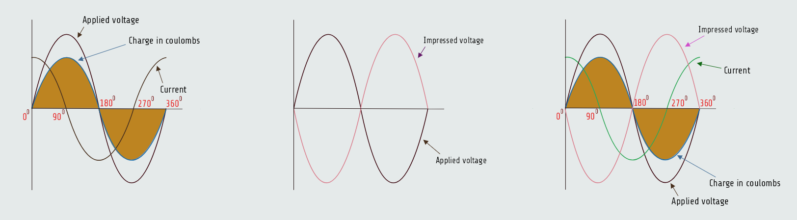
Power in a pure capacitive circuit
Since the current flow in a pure capacitive circuit leads the applied voltage by 90°, the voltage and current have the same polarity for half the time during one cycle and have opposite polarities the other half of the time, represented on the figure below.
During the period of time that the voltage and current have the same polarity, energy is being stored in the capacitor in the form of an electrostatic field. When the voltage and current have opposite polarities, the capacitor is discharging and the energy is returned to the circuit. When the values of current and voltage for one full cycle are added, the sum equals zero just as it does with pure inductive circuits. Therefore, there is no true power, or watts, produced in a pure capacitive circuit. 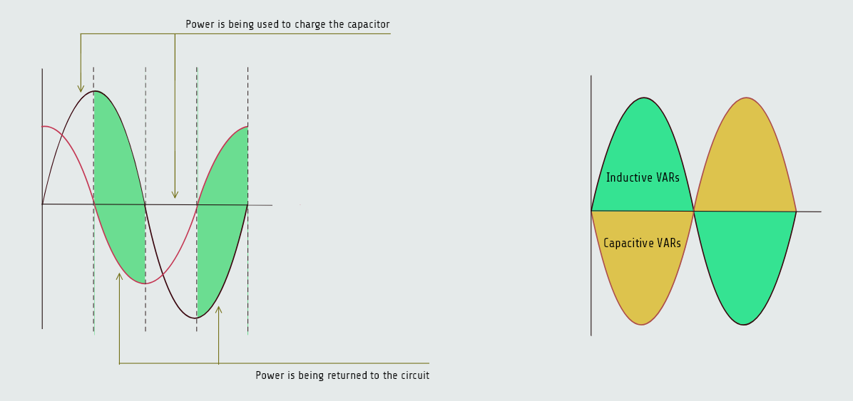
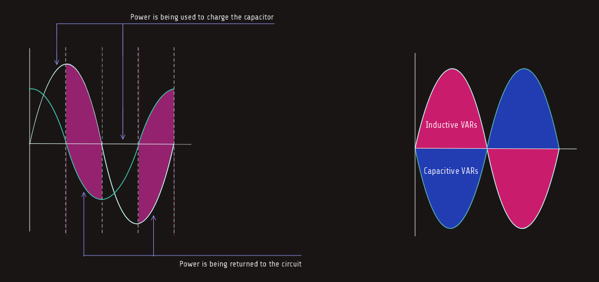 The power value for a capacitor is reactive power and is measured in VARs, just as it is for an inductor. Inductive VARs and capacitive VARs are 180° out of phase with each other, however.
The quality (Q) of a capacitor is generally very high and for a real-world capacitor, the quality factor is the ratio of its energy-storing capability to its energy-wasting reality Q = XC/R. XC is the Capacitive Reactance (the bounce / stored energy), R is the Equivalent Series Resistance (ESR) (the friction / wasted energy).
If we are jumping, for example, on a trampoline, our goal is to bounce as efficiently as possible. XC represents the capacitor’s ability to temporarily store our kinetic energy and launch us back up.
A good trampoline mat stretches, stores the energy of our landing, and returns it to us. This is the reactive, non-dissipative part of the system. It doesn't consume energy; it just trades it back and forth.
No matter how good the mat is, the springs holding it to the frame have friction, air resistance, and rust. Every time we land, some of our energy is lost as heat and sound.
This is the ESR, Equivalent Series Resistance (R). It is the unwanted, stubborn resistance inside the capacitor (from leads, plates, and dielectric losses) that turns our electrical energy into useless heat.
Q is simply the ratio of Bounce XC to Friction R.