


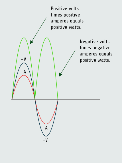
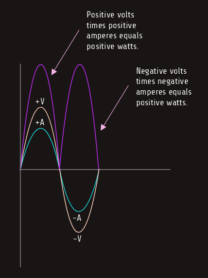
Power in an AC circuit
True power (watts) can be produced only when both current and voltage are either positive or negative. Since the current and voltage are both either positive or negative at the same time, the product, watts, is always positive.
Skin effect
We have mentioned before that when current flows through a conductor connected to a source of DC, the electrons flow through the entire conductor. The conductor offers some amount of ohmic resistance to the flow of electrons depending on the type of material from which the conductor is made, its length, and its diameter. If that same conductor were connected to a source of AC, the resistance of the conductor to the flow of current would be slightly higher because of the skin effect. The AC induces eddy currents into the conductor. These eddy currents cause the electrons to be repelled toward the outer surface of the conductor. This phenomenon is called the skin effect. Forcing the electrons toward the outer surface of the conductor has the same effect as decreasing the diameter of the conductor, which increases conductor resistance.
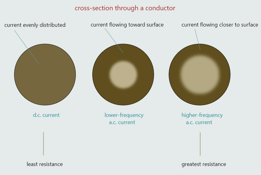
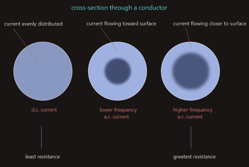
The skin effect is proportional to the frequency. As the frequency increases, the skin effect increases. At low frequencies, such as 50 hertz, the skin effect has very little effect on the resistance of a conductor and generally is not taken into consideration when computing the size wire needed for a particular circuit. At high frequencies, however, the skin effect can have a great effect on the operation of the circuit. It can be reduced, though, by using conductors with a large surface area.
Inductance in AC circuits
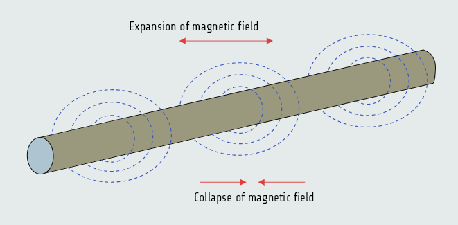
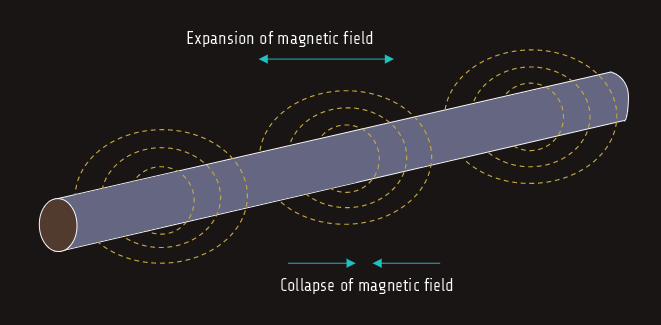
Inductance is one of the three major types of loads found in alternating current circuits. Some amount of inductance is present in all AC circuits because of the continually changing magnetic field. The amount of inductance of a single conductor is extremely small, usually not considered in circuit calculations; circuits are generally considered to contain inductance when any type of load that contains a coil is used. We already know that whenever current flows through a coil of wire a magnetic field is created around the wire - if the amount of current decreases, the magnetic field collapses, while increasing the amount of current expands the magnetic field.
1. When magnetic lines of flux cut through a coil, a voltage is induced in the coil.
2. An induced voltage is always opposite in polarity to the applied voltage (counter-electromotive force - CEMF).
3. The amount of induced voltage is proportional to the rate of change of current.
4. An inductor opposes a change of current.
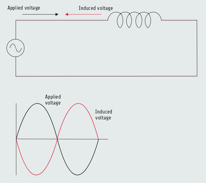
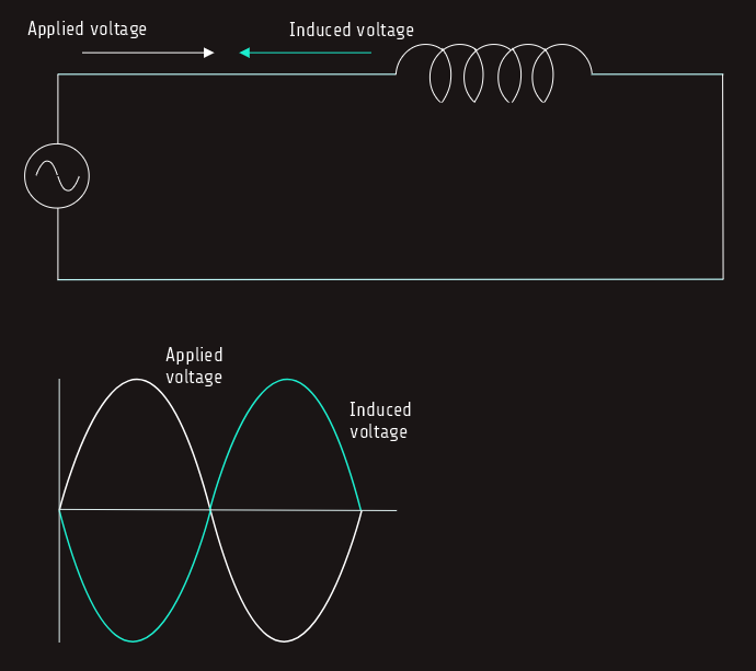
For an inductor connected to an alternating voltage, the magnetic field continually increases, decreases, and reverses polarity. Since the magnetic field continually changes magnitude and direction, a voltage is continually being induced in the coil. This induced voltage is 180° of phase with the applied voltage and is always in opposition to the applied voltage.
Since the induced voltage is always in opposition to the applied voltage, the effective applied voltage is reduced by the induced voltage.
For example, assume an inductor is connected to a 120-volts AC line. Now assume that the inductor has an induced voltage of 116 volts. Since the induced voltage subtracts from the applied voltage, there is only 4 volts to push current through the wire resistance of the coil.
Inductive reactance
Induced voltage is able to limit the flow of current through the circuit in a manner similar to resistance. This induced voltage is not resistance, but it can limit the flow of current just as resistance does. This current-limiting property of the inductor is called reactance and is symbolized by the letter X. This reactance is caused by inductance, so it is called inductive reactance and is symbolized by XL. Inductive reactance is measured in ohms just as resistance is and can be computed when the values of inductance and frequency are known.
XL = 2πfL • XL - inductive reactance
• 2 - constant
• π - 3.14
• f - frequency (Hz)
• L - inductance (H)
The inductive reactance is caused by the induced voltage and is, therefore, proportional to the three factors that determine induced voltage:
1. the number of turns of wire
2. the strength of the magnetic field
3. the speed of the cutting action (relative motion between the inductor and the magnetic lines of flux)
The number of turns of wire and the strength of the magnetic field are determined by the physical construction of the inductor.
Factors such as the size of wire used, the number of turns, how close the turns are to each other, and the type of core material determine the amount of inductance of the coil. Coils with turns closer together produce more inductance than coils with turns far apart. The inductance of the coil is determined by its physical construction, it does not change when connected to a different frequency.
The speed of the cutting action is proportional to the frequency. An increase of frequency causes the magnetic lines of flux to cut the conductors at a faster rate and, thus, produces a higher induced voltage or more inductive reactance.
Example:
Assume an inductor with a negligible resistance is connected to a 36-V, 400-Hz line. If the circuit has a current flow of 0.2 A, what is the inductance of the inductor?
Solution:
Let's first determine the inductive reactance of the circuit.
Since inductive reactance is the current-limiting property of this circuit, it can be substituted for the value of R in an Ohm’s law formula:
XL = E/I
XL = 36/0.2 = 180 [Ω]
Now that the inductive reactance of the inductor is known, the inductance can be determined: XL=2πfL ⇒ L=XL/2πf = 180/(2·3,14·400)
L = 0,0716 [H]
Series and parallel connection
When inductors are connected in series, the total inductance of the circuit (LT) equals the sum of the inductances of all the inductors:
LT = L1+L2+L3
The total inductive reactance (XLT) of inductors connected in series equals the sum of the inductive reactances for all the inductors:
XLT = XL1+XL2+XL3
When inductors are connected in parallel, the reciprocal of the total inductance is equal to the sum of the reciprocals of all the inductors:
1/LT = 1/L1+1/L2+1/L3
Another formula that can be used is product-over-sum formula:
LT = (L1xL2)/(L1+L2)
If the values of all the inductors are the same, total inductance can be found by dividing the inductance of one inductor by the total number of inductors:
LT = L/N
Similar formulas can be used to find the total inductive reactance:
1/XLT = 1/XL1+1/XL2+1/XL3
XLT = (XL1xXL2)/(XL1+XL2)
XLT = XL/N