


The average velocity at which free electrons drift past any given point within a conductor is known as their ‘drift velocity’. So, we can ask a question: If the drift of charge carriers really is so very slow, then why does a lamp illuminate immediately when its switch is operated? Why isn’t there a delay between operating the switch and the lamp coming on?
The answer is that free electrons are not waiting behind the switch, of course - ready to pour into the circuit. Rather, they are permanently distributed throughout the entire length of the conductor (they were there before the raw copper was made into a conductor) and, while their individual progress may be very slow, all those free electrons are moving at the same time. So the effect of the current is felt immediately around the entire circuit. It's easy to visualize this by comparing this behaviour with that of a row of coupled railway goods wagons. A very small force applied to the wagon at one end of the row will cause a near-instantaneous movement of the wagon at the far end of the row, even though the individual wagons will have moved only a very short distance. We have seen earlier similar example with the table-tennis balls.
It’s very important to understand that, despite having enormous quantities of free electrons, a conductor normally remains electrically neutral. This is because, for every single electron (whether ‘free’ or orbiting within a shell) within the conductor, there is always a corresponding proton within the fixed atoms.
So, when a free electron exits the conductor at the end connected to an external positive charge, in order to maintain the conductor’s neutrality, another free electron is instantaneously drawn into the conductor from the end connected to the external negative charge.
Except from metallic conductors, discussed earlier, there are also conductors that are liquids or gases (conducting liquids are called ‘electrolytes’). Unlike solids, the atoms in electrolytes are loosely bound together, and are themselves free to move around. So, current flow through electrolytes is not due to a drift of electrons, but due to a drift of ions (charged atoms). In electrolytes, a current is not only a drift of ions but, often, a drift of both positive and negative ions which move in opposite directions to each other at the same time! Despite this, it is conventional to assume the direction of ‘current’ within an electrolyte is the direction in which the positive ions move.
As electrons and ions are generically described as ‘charge carriers’, it would be more accurate, therefore, to describe an electric current as a drift of charge carriers.
This definition of current will then apply to solid, liquid or gaseous conductors.
Drift of charges, explained above, is termed a ‘conduction current’, because there is another type of current, termed a ‘displacement current’. The unit of measurement of electric current is the ampere (symbol: A), which is one of the seven SI base units.
Displacement current in insulators or dielectrics
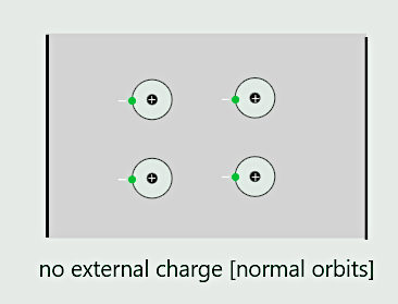
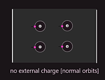
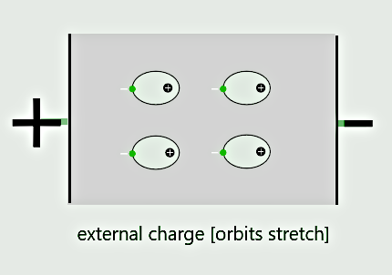
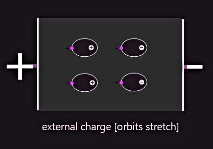
There are relatively few free electrons available as charge carriers in insulators; so, within these materials the drift of free electrons is insignificantly small. This tiny drift of electrons is known as ‘leakage current’. Something very interesting happens to the fixed atoms when external charges are applied across a sample of insulator. The atoms themselves cannot move but, under the influence of external charges, the shape of the orbits of their electrons can! The orbits of the electrons within a sample of insulator become distorted, or ‘stretched’, towards the positive external charge. We say that the atoms have become ‘polarized’. The greater the difference between the external charges, the greater the amount of distortion.
  |
  |
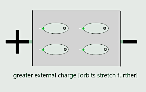 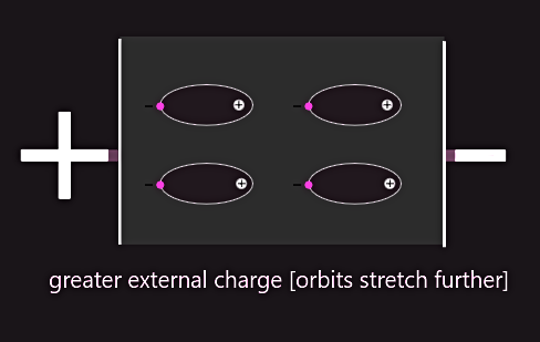 |
This ‘stretching’ of the electron orbits represents a momentary current, which we call a ‘displacement current’. So, a displacement current only takes place during any change to the magnitude of the external charges. If an alternating voltage were applied across an insulating material, then it would be accompanied by a continuous displacement current that would vary in both magnitude and direction, just like that voltage.
A ‘displacement current’, then, is associated with insulators, and is a ‘momentary’ current due to the distortion of the fixed atoms’ electron orbits under the influence of external electric charges, whereas a ‘conduction current’ is a current due to the movement of free charges (electrons, in the case of metal conductors) through a conductor, or as a tiny ‘leakage current’ through an insulator.
'Electron flow' versus 'conventional current' flow
By ‘direction of current’ in metallic conductors, we mean the direction in which current passes through the load, the direction through the external circuit, never within the source of potential difference.
During the eighteenth century, the great American scientist and statesman Benjamin Franklin (1706–1790), along with others, believed that an electric current was some sort of mysterious ‘fluid’ that flowed inside a conductor from high-pressure area to low-pressure area. He naturally labelled high pressure as being ‘positive’ pressure, and low pressure as being ‘negative’ pressure and so he believed that the direction of an electric current was from ‘positive to negative’ – i.e. in a direction opposite to that of the drift of free electrons!
Most electronic circuits use the negative terminal as ground or common. So, the negative terminal is used as ground and positive terminal is then 'above the ground' (most people consider the positive battery terminal as being the hot terminal), and current flows from positive to negative terminal. We can think of it as current flows from above the ground to the ground (from positive to negative terminal) rather then vice-versa (from negative to positive). It is also used in electronics, where all arrows of semiconductor symbols point in the direction of conventional current flow.
Good example of this type of circuit is automobile electric system.
Franklin’s mistaken theory on current direction was reinforced during the following century, as a result of experiments in electrolysis conducted by the English scientist Michael Faraday (1791–1867). Electrolysis is a method of depositing ('plating') metal on an electrode immersed in an electrolyte. Faraday noticed during his experiments that metal was removed from the positive electrode and deposited on the negative electrode, from which he, too, concluded that the current direction was from positive to negative, although he rejected Franklin’s idea that it was a ‘fluid’, in favour of it being a ‘field’.
Franklin’s current direction is still widely used as a convention and is known as ‘Franklinian’ or, more commonly, conventional flow. Following Franklin’s belief that his ‘electric fluid’ moved from a higher pressure to a lower pressure, whenever we use conventional flow, we say that the direction of current is from a higher potential to a lower potential. In other words, a more-positive potential is considered to be a higher potential than a more-negative potential.
Practical conductors and insulators
There is no such thing as a ‘perfect’ conductor or a ‘perfect’ insulator (‘dielectric’).
Even the best insulators contain impurities, and these impurities contribute a relatively small number of free electrons, which enable tiny currents to flow. Furthermore, thermal activity causes free electrons to be generated within most insulators. So, in practice, there is simply no such thing as a ‘perfect’ insulator and at high temperatures, even the best insulator will break down and conduct.
In practical terms, the very best metallic conductor is silver which, because of its cost, is only used for special applications such as relay contacts and printed circuit boards. The most commonly used conductors are copper and aluminium; copper comes a close second to silver and is a better conductor than aluminium but far more expensive – which is why (together with its lower mass) aluminium is preferred for high-voltage transmission and distribution line conductors.
Most practical insulators are compounds rather than elements and include toughened glass and ceramics (used to insulate overhead power lines), certain gases (used to insulate high-voltage busbars), mineral oils (used to insulate high-voltage transformers and circuit breakers), or oil-impregnated paper and plastics (used to insulate electric cables).
It’s important to emphasize that an insulator doesn’t ‘oppose’ an electric current. Rather, it simply doesn’t have sufficient charge carriers available to support an electric current.
Electric current
We learnt earlier that electric current is ‘the quantity of electric charge, transported per unit time’ (free electrons, in the case of a metal conductor). This current is driven by external negative and positive charges or, more accurately, by the electric field that exists between those external charges. We can imagine electric field as imaginary lines of force stretching between the external charges and along which the mobile charge carriers slowly drift. In the case of solid metal conductors, it’s a drift of free electrons. In other materials, such as conducting liquids (‘electrolytes’) or ionised gas, it’s a drift of ions (charged atoms).
Without the electric field, the movement of the electric charges would be completely random. But, under the influence of an electric field, there is a drift of electric charge in a particular direction and this constitutes an electric current. The presence of a current can only be detected by observing one or more of the three effects produced by that current:
• heating effect
• chemical effect
• magnetic effect
|
Heating effect – an electric current causes a conductor’s temperature to rise. This effect in practice is used with incandescent lamps, electric heaters, etc. It is also responsible for the operation of fuses, which melt in response to rises in temperature due to excessively high currents. This effect is also responsible for wasteful energy losses, due to heat transfer away from a conductor into its surroundings. |
Chemical effect – an electric current can be responsible for chemical reactions. This effect is used in electrolysis (electroplating) – but it may also be harmful, as it is also responsible for some types of corrosion. |
Magnetic effect – an electric current produces a magnetic field, which surrounds the conductor through which that current passes. The resulting effect from the interactions between magnetic fields is used to drive motors, operate relays, etc. |
As we have learnt, the SI unit of measurement of electric current is the ampere (symbol: A).
Since 1947, the definition of the ampere is based on the force resulting from the magnetic effect of an electric current, as follows:
The ampere (symbol: A) is defined as ‘that constant current which, when maintained in two straight parallel conductors of infinite length and of negligible circular cross-sectional area, and placed one metre apart in a vacuum, would produce between them a force equal to 2×10⁻⁷ newton per metre of length’.
The ‘force’ referred to in this definition is due to the attraction or repulsion (depending in the relative current directions, as seen in figure below) between two parallel conductors, due to the interaction of the magnetic fields set up around the currents drifting through those conductors.
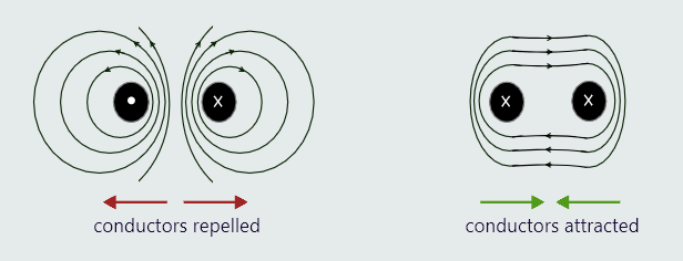
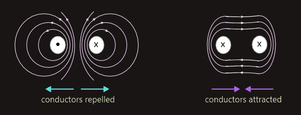
The dot indicates conventional current drifting towards us and the cross represents conventional current drifting away from us, and the lines represent the shape of the resulting magnetic fields.
Electric charge
So far, charges have been described as being either ‘positive’ or ‘negative’, without making any attempt to assign any values to them. So how is electric charge measured?
The smallest quantity of charge must be the amount of negative charge possessed by an individual electron which, of course, is exactly the same as the amount of positive charge possessed by an individual proton. The amount of charge on an individual electron is so incredibly tiny, so we need to use a much larger and more practical unit for measuring electric charge. Electric charge is defined in terms of the amount of charge transported, per second, by a current of one ampere, and the name given to this amount of charge is the coulomb (symbol: C), named in honour of the French academic, Charles de Coulomb (1736–1806).