


DC Motor
A DC motor is an electrical machine that converts electrical energy into mechanical energy. In a DC motor, the input electrical energy is the direct current which is transformed into the mechanical rotation. Theoretically, the same DC machine can be used as a motor or generator. Therefore, construction of a DC motor is same as that of a DC generator.
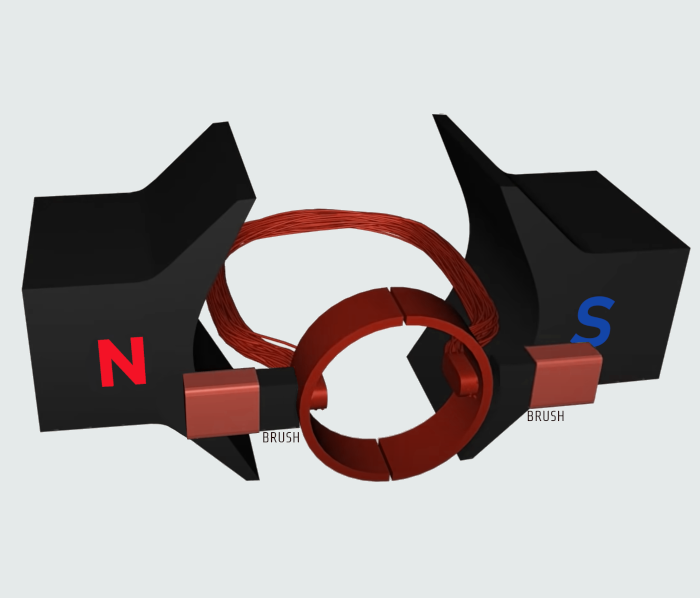
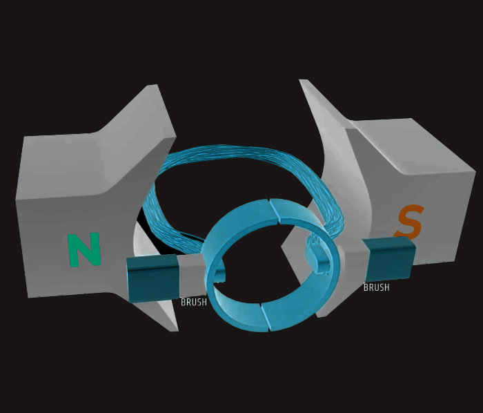

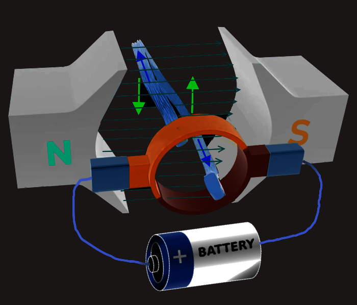
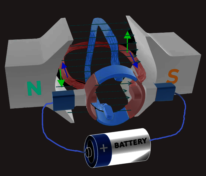
The stator is a permanent magnet and provides a constant magnetic field. The armature, which is the rotating part, is a simple coil.
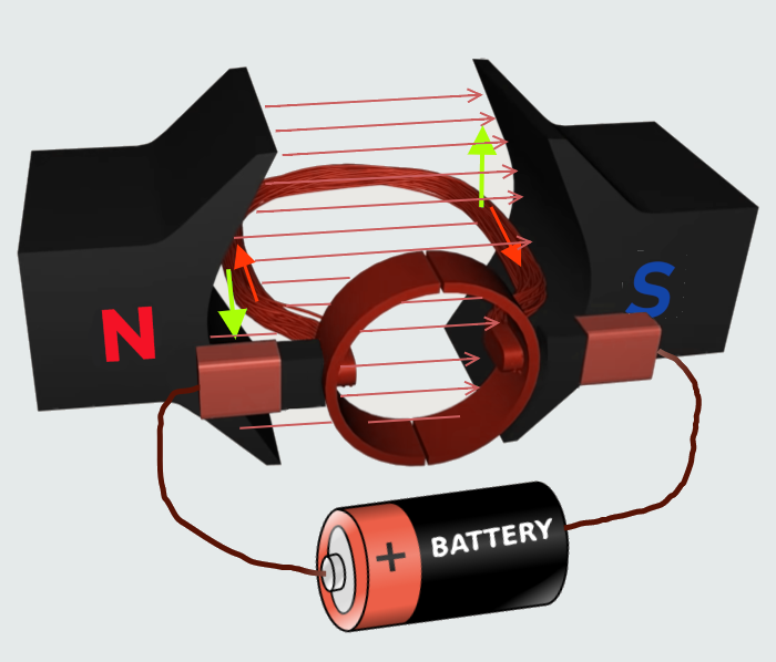
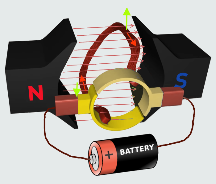
The basic working principle of a DC motor is: "whenever a current carrying conductor is placed in a magnetic field, it experiences a mechanical force". The direction of this force is given by Fleming's left-hand rule and its magnitude is given by F = BIL, where: B = magnetic flux density, I = current and L = length of the conductor within the magnetic field. The armature is connected to a DC power source through a pair of commutator rings. When the current flows through the coil an electromagnetic force is induced on it according to the Lorentz law, so the coil will start to rotate.
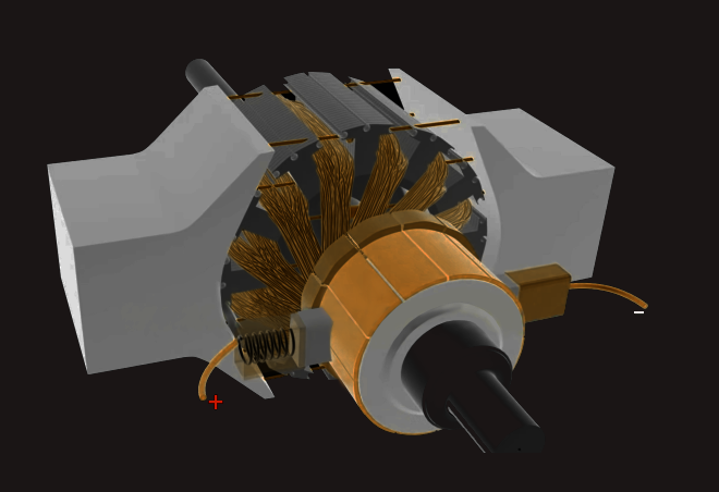
Armature or Rotor
The armature of a DC motor is a cylinder of magnetic laminations that are insulated from one another. The armature is perpendicular to the axis of the cylinder. The armature is a rotating part that rotates on its axis and is separated from the field coil by an air gap.
Field Coil or Stator
A DC motor field coil is a non-moving part on which winding is wound to produce a magnetic field. This electro-magnet has a cylindrical cavity between its poles.
Commutator and Brushes
Commutator
The commutator of a DC motor is a cylindrical structure that is made of copper segments stacked together but insulated from each other using mica. The primary function of a commutator is to supply electrical current to the armature winding.
Brushes
The brushes of a DC motor are made with graphite and carbon structure. These brushes conduct electric current from the external circuit to the rotating commutator. Hence, we come to understand that the commutator and the brush unit are concerned with transmitting the power from the static electrical circuit to the mechanically rotating region or the rotor.
As the coil rotates, the commutator rings connect with the power source of opposite polarity. As a result, on the left side of the coil the electricity will always flow ‘away‘ and on the right side, electricity will always flow ‘towards‘. This ensures that the torque action is also in the same direction throughout the motion, so the coil will continue rotating.
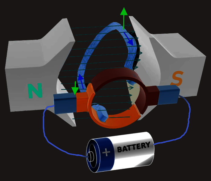
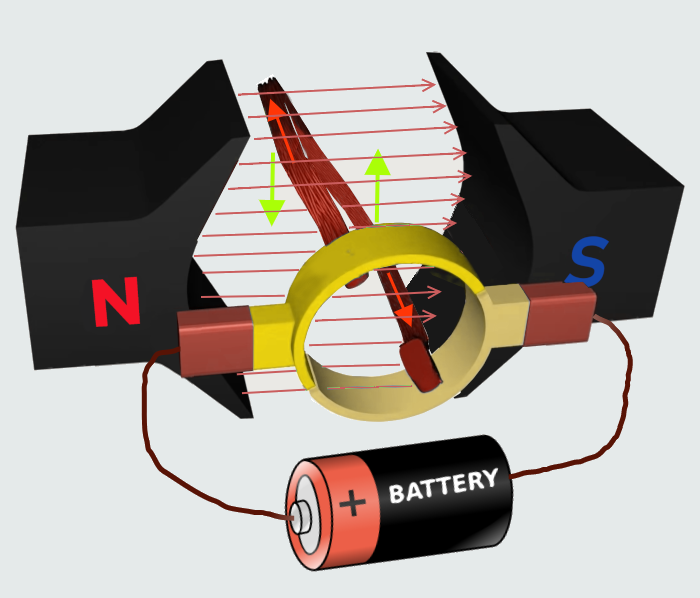
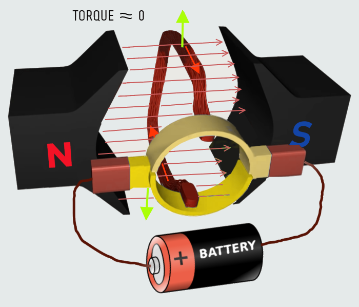
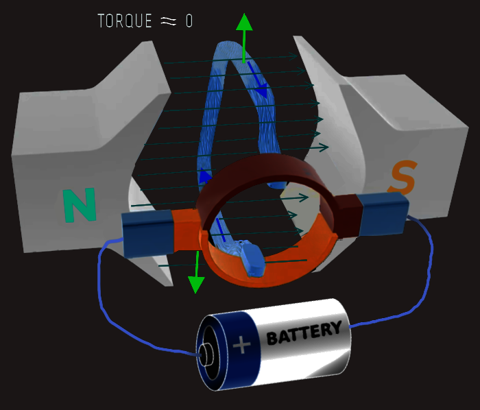
But if we observe the torque action on the coil closely, we will notice that, when the coil is nearly perpendicular to the magnetic flux, the torque action nears zero. As a result there will be irregular motion of the rotor, that could be solved by adding one more loop to the rotor, with a separate commutator pair for it. In this arrangement when the first loop is in the vertical position, the second loop will be connected to the power source. So a motive force is always present in the system.
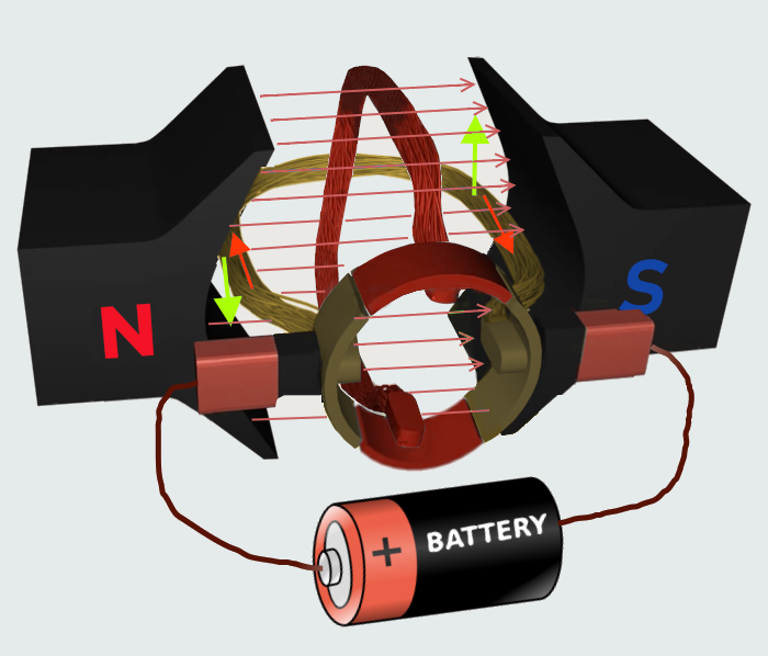
Moreover, the more such loops, the smoother will be the motor rotation.
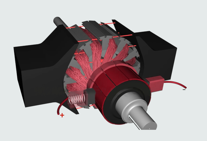
In a practical motor, the armature loops are fitted inside slots of highly permeable steel layers. This will enhance magnetic flux interaction. Spring loaded commutator brushes help to maintain contact with the power source.
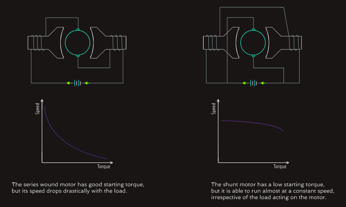
Magnetic field may be provided by field winding (electromagnetism) or by using permanent magnets. Most often, instead of the permanent magnets, an electromagnet is used; the field coil of the electromagnet is powered from the same DC source. The field coils can be connected to the rotor windings in 2 different ways; parallel or series. This results into 2 different kinds of DC motor constructions; a shunt and a series motors. Copper wire is used for the construction of field coils. When the DC is passed through the field windings, it magnetizes poles that produce magnetic flux. The connection of the field winding and the armature winding is done according to the type of the motor and decides the characteristics of the motor. 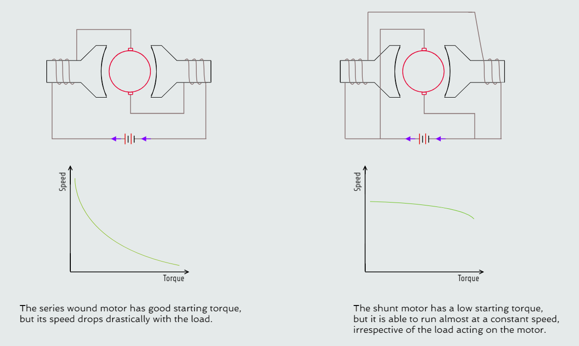
 Unlike the other electrical machines DC motors exhibit a unique characteristic; the production of back EMF. A rotating loop in magnetic field will produce an EMF according to the principle of electromagnetic induction. An internal EMF will be induced that opposes the applied input voltage. The back EMF reduces armature current by a large amount. Back EMF is proportional to the speed of the rotor. At the starting of the motor, back EMF is too low, thus the armature current becomes too high, leading to burnout of the rotor. Thus a proper starting mechanism that controls the applied input voltage is necessary in large DC motors.