


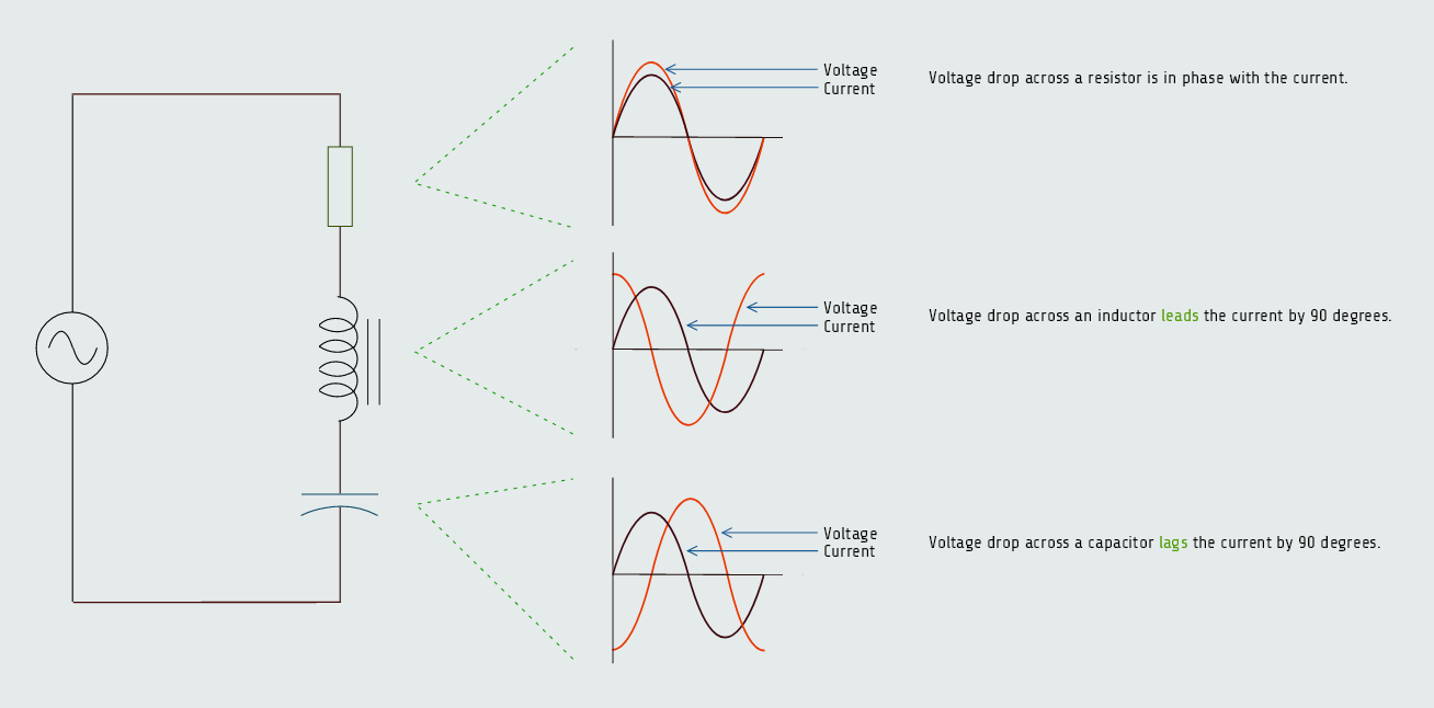
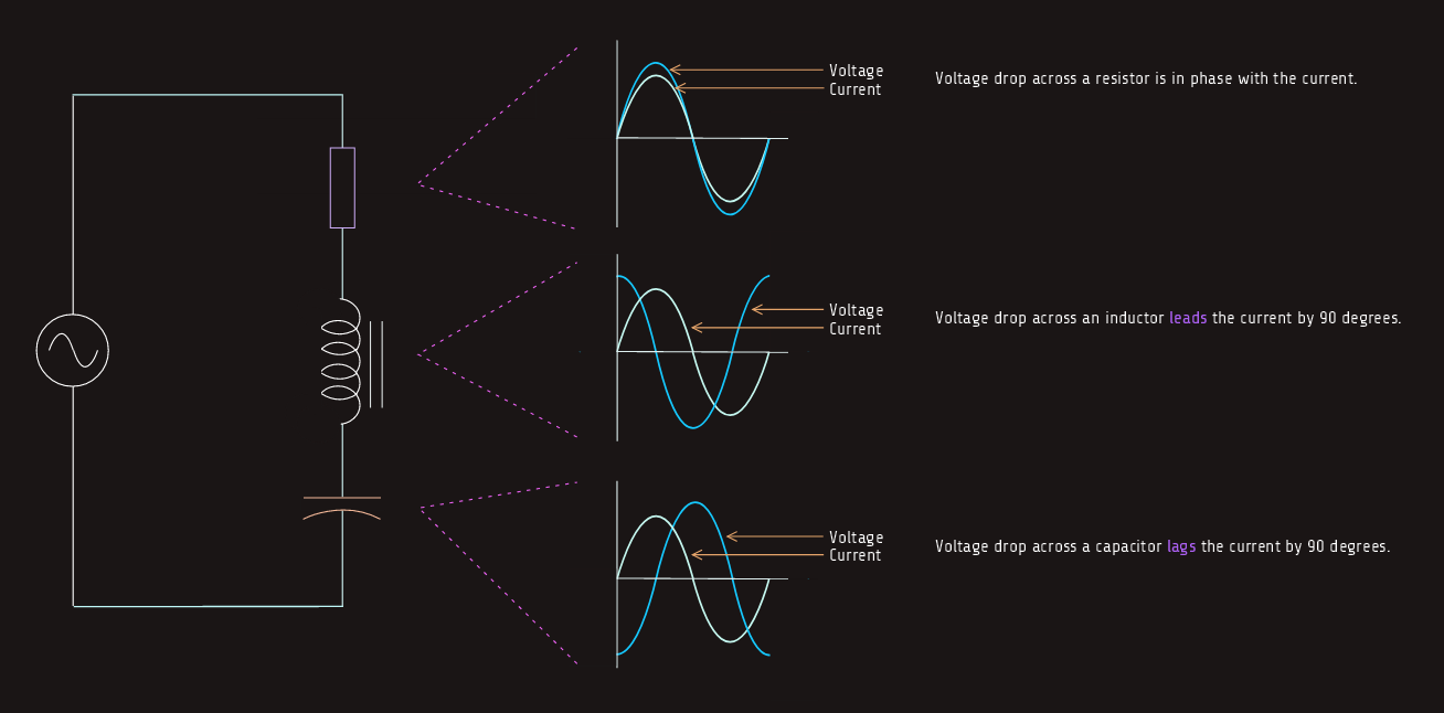
Total Impedance
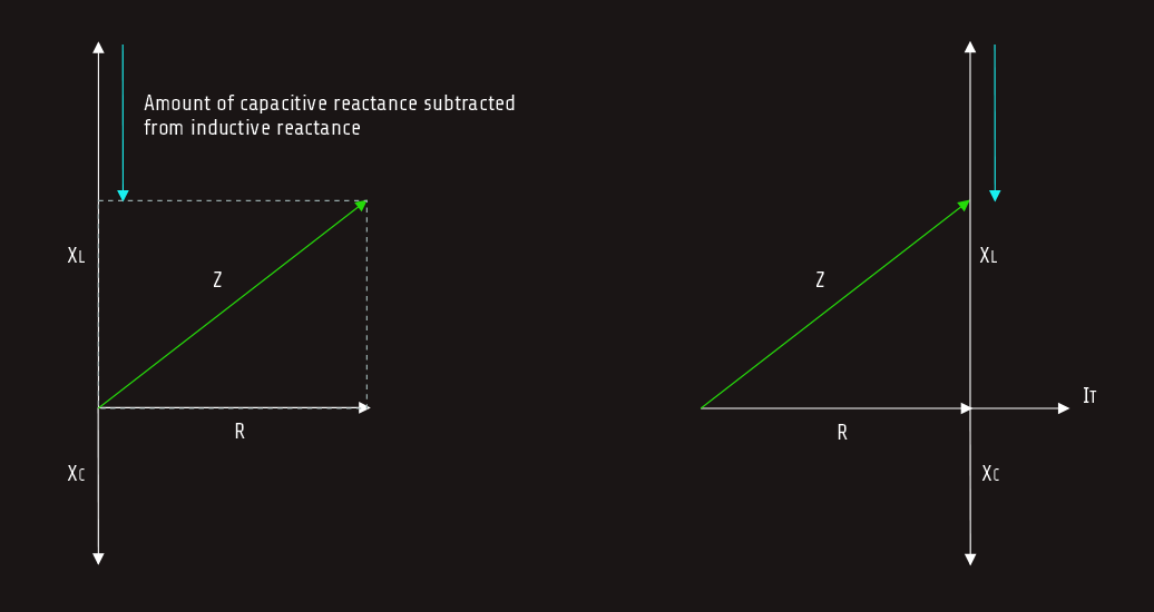
The impedance of the circuit is the sum of resistance, inductive reactance, and capacitive reactance. Since inductive reactance and capacitive reactance are 180° out of phase with each other, vector addition must be used to find their sum. This method results in the smaller of the two reactive values being subtracted from the larger. The smaller value is eliminated, and the larger value is reduced by the amount of the smaller value. The total impedance is the hypotenuse formed by the resulting right triangle. The impedance is computed by using the formula:
Z = √(R2 + (XL-XC)2)
Here we see that the capacitive reactance is subtracted from the inductive reactance and then the difference is squared. If the capacitive reactance is a larger value than the inductive reactance, the difference is a negative number. The sign of the difference has no effect on the answer, however, because the square of a negative or positive number is always positive. 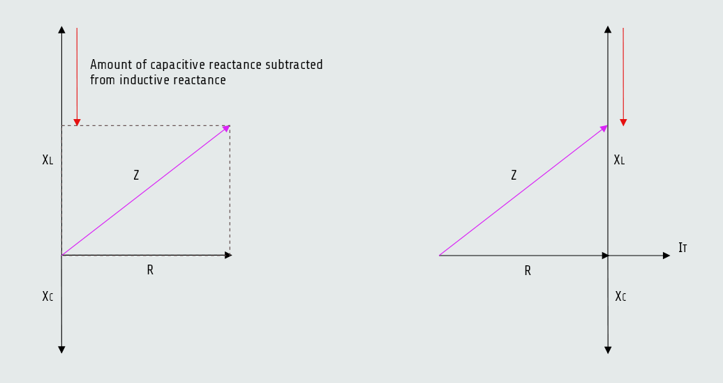
 The apparent power can also be found by vector addition of true power, inductive VARs, and capacitive VARs. As with the addition of resistance, inductive reactance, and capacitive reactance, inductive VARs, VARsL, and capacitive VARs, VARsC are 180° out of phase with each other. The result is the elimination of the smaller and a reduction of the larger. The following formula can be used to determine apparent power:
VA = √(P2 + (VARsL-VARsC)2)
Series resonant circuits
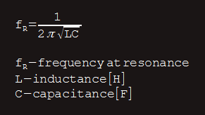
When an inductor and capacitor are connected in series, there is one frequency at which the inductive reactance and capacitive reactance become equal. We know that as frequency increases, inductive reactance increases and capacitive reactance decreases. The point at which the two reactances become equal is called resonance.
Resonant circuits are used to provide great increases of current and voltage at the resonant frequency.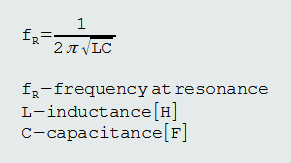
 So, the two reactances become equal and opposite in direction and the only current-limiting factor in the circuit is the wire resistance in the coil.
During the period of time that the circuit is not at resonance, current flow is limited by the combination of inductive reactance and capacitive reactance, and the total impedance can be found using previous formula, mentioned above. 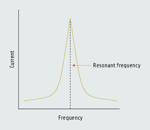
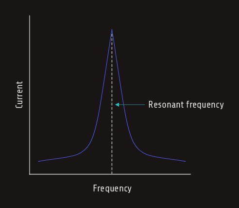 We can see in this graph thatthe current increases sharply at the resonant frequency.
Besides, the voltage drops across the inductor and capacitor increase at resonance. Although inductive and capacitive reactance cancel each other at resonance, each is still a real value. Both the inductive reactance and capacitive reactance have an ohmic value at the resonant frequency.
Bandwidth
The rate of current increase and decrease is proportional to the quality (Q) of the components in the circuit. High-Q components result in a sharp increase of current as illustrated above. Not all series resonant circuits produce as sharp an increase or decrease of current as illustrated in figure above. The term used to describe this rate of increase or decrease is bandwidth.
B = fR/Q B - bandwidth
Q - quality of circuit components
fR - frequency at resonance
Bandwidth is a frequency measurement.
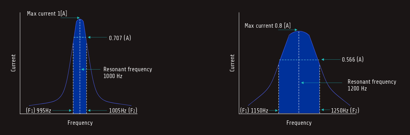
B = f2-f1It is the difference between the two frequencies at which the current is at a value of 0.707 of the maximum current value.
When resonant circuits are constructed with components that have a relatively high Q, the difference between the two frequencies is small. These circuits are said to have a narrow bandwidth.
In a resonant circuit using components with a lower Q rating, the current does not increase as sharply. In this circuit, it is assumed that resonance is reached at a frequency of 1200 hertz and the maximum current flow at resonance is 0.8 ampere. The bandwidth is determined by the difference between the two frequencies at which the current is at a value of 0.566 ampere (0.8 A x 0.707 = 0.566 A). Assume the lower frequency to be 1150 hertz and the upper frequency to be 1250 hertz. This circuit has a bandwidth of 100 hertz (1250 Hz - 1150 Hz = 100 Hz) and this circuit is said to have a wide bandwidth. 
 A narrow-band resonant circuit is produced by high-Q inductors and capacitors, a wide-band resonant circuit is produced by low-Q inductors and capacitors.