


Example:
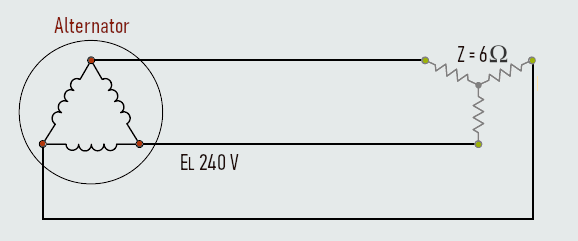
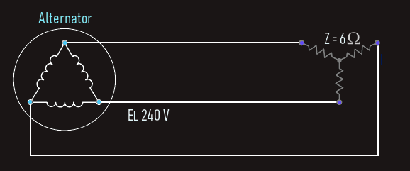
A delta-connected alternator is connected to a wye-connected resistive load. The alternator produces a line voltage of 240 V and the resistors have a value of 6 Ω each. Calculate another circuit values...
Solution:
The load is connected directly to the output of the alternator. The line voltage of the load must, therefore, be the same as the line voltage of the alternator.
EL(load) = 240 V
The phase voltage of a wye connection is less than the line voltage by a factor of 1.732:
EP(load) = EL(load)/1.732 = 138.57 V
Each of the three 6-Ω resistors is one phase of the wye-connected load. Since the phase voltage is 138.57 V, this voltage is applied to each of the three resistors.
IP(load) = EP(load)/Z
IP(load) = 138.57/6 = 23.1 A
The amount of line current needed to supply a wye-connected load is the same as the phase current of the load.
IL(load) = IP(load) = 23.1 A
The line current supplied to the load is the same as the line current of the alternator.
IL(alt) = 23.1 A
The phase windings of the alternator are connected in delta. In a delta connection the phase current is less than the line current by a factor of 1.732:
IP(alt) = IL(alt)/1.732 = 23.1/1.732 = 13.34 A
The phase voltage of a delta is the same as the line voltage.
EP(alt) = EL(alt) = 240 V
Since the load in this example is pure resistive, the power factor has a value of unity, or 1. Power will be computed by using the line values of voltage and current.
P = √3 x EL x IL x PF
P = 1.732 x 240 x 23.1 x 1 W
P = 9,602.21 W
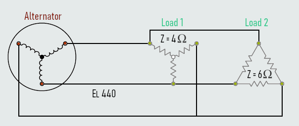
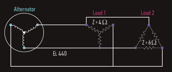
Example:
The phase windings of an alternator are connected in wye. The alternator produces a line voltage of 440 V, and supplies power to two resistive loads. One load contains resistors with a value of 4 Ω each, connected in wye. The second load contains resistors with a value of 6 Ω each, connected in delta. Calculate another circuit values...
Solution:
Both loads are connected directly to the output of the alternator. The line voltage for both loads 1 and 2 will be the same as the line voltage of the alternator.
EL(load1) = 440 V
EL(load2) = 440 V
Load 2 is connected as a delta. The phase voltage will be the same as the line voltage.
EP(load2) = 440 V
Each of the resistors that constitutes a phase of load 2 has a value of 6 Ω. The amount of phase current can be found using Ohm’s Law.
IP(load2) = EP(load2)/Z
IP(load2) = 440/6
IP(load2) = 73.33 A
The line current supplying a delta-connected load is 1.732 times greater than the phase current.
IL(load2) = IP(load2) x 1.732
IL(load2) = 127.01 A
The resistors of load 1 are connected to form a wye. The phase voltage of a wye connection is less than the line voltage by a factor of 1.732.
EP(load1) = EL(load1)/1.732
EP(load1) = 440/1.732 V = 254.04 V
Now the phase current can be computed using Ohm’s Law.
IP(load1) = EP(load1)/Z
IP(load1) = 254.04/4 A
IP(load1) = 63.51 A
The line current supplying a wye-connected load is the same as the phase current.
IL(load1) = IP(load1)
IL(load1) = 63.51 A
The alternator must supply the line current needed to operate both loads. In this example, both loads are resistive. The total line current supplied by the alternator will be the sum of the line currents of the two loads.
IL(alt) = IL(load1) + IL(load2)
IL(alt) = 63.51 A + 127.01 A
IL(alt) = 190.52 A
The phase voltage of the alternator will be less than the line voltage by a factor of 1.732.
EP(alt) = EL(alt)/1.732
EP(alt) = 254.04 V
Both of the loads in this example are resistive and have a unity power factor of 1. The total power in this circuit can be found by using the line voltage and total line current supplied by the alternator.
P = √3 x EL x IL x PF
P = 1.732 x 440 x 190.52 x 1 W
P = 145,191.48 W
The power in a 3-phase balanced load is obtained by multiplying the power in one phase by 3. In many practical situations, it is more convenient to work with line quantities, though.
Pph = Uph x Iph x cosΦ
cosΦ - phase power factor
Total power is: P = 3 x Pph
Now, for a star-connected load: Uph = Uline/√3 and Iph = Iline, and for a delta-connected load: Uph = Uline and Iph = Iline/√3.
Substituting these values into above equation will yield the same result in both cases:
P = 3 x Uline/√3 x Iline x cosΦ or P = 3 x Uline x Iline/√3 x cosΦ
P = √3 x Uline x Iline x cosΦ
Thus, the equation for determining power dissipation, in both star and delta-connected loads is exactly the same. However, the value of power dissipated by a given load when connected in star is not the same as when it is connected in delta. It can be shown in some practical example that power in a delta-connected load is three times that when it is connected in star configuration.
We already know that the distribution of 3-phase supplies is normally at a much higher line voltage than that required for many users. Hence, 3-phase transformers are used to step the voltage down to the appropriate value. A three-phase transformer is basically three single-phase transformers interconnected. The three primary windings may be connected either in star or delta, as can the three secondary windings. Similarly, the load connected to the transformer secondary windings may be connected in either configuration. One important point to bear in mind is that the transformation ratio (voltage or turns ratio) refers to the ratio between the primary phase to the secondary phase winding.
Also, in short lines here, if a three-phase load is balanced, then it is necessary only to measure the power taken by one phase. The total power of the load is then obtained by multiplying this figure by three, whereas in an unbalanced load, separate readings must be taken into account for each phase and then calculate the total power as the sum of separate readings. We shall remember that the procedure is not the same for a star-connected and delta-connected load.
Another fact that we have already seen is that the neutral current for a balanced load is zero. This is because the phasor sum of three equal currents, mutually displaced by 120°, is zero. If the load is unbalanced, then the three line (and phase) currents will be unequal. In this case, the neutral has to carry the resulting out-of-balance current. This current is simply obtained by calculating the phasor sum of the line currents. The technique is basically the same as that used previously, by resolving the phasors into horizontal and vertical components, and applying Pythagoras’ theorem. The only additional fact to bear in mind is that both horizontal and vertical components can have negative values.