


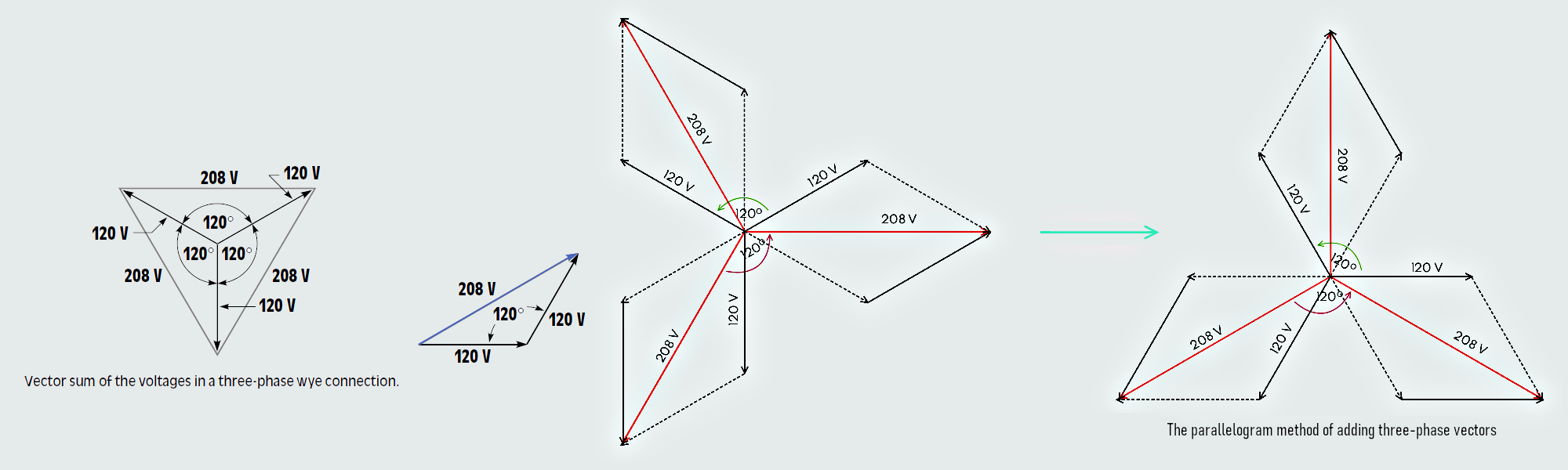
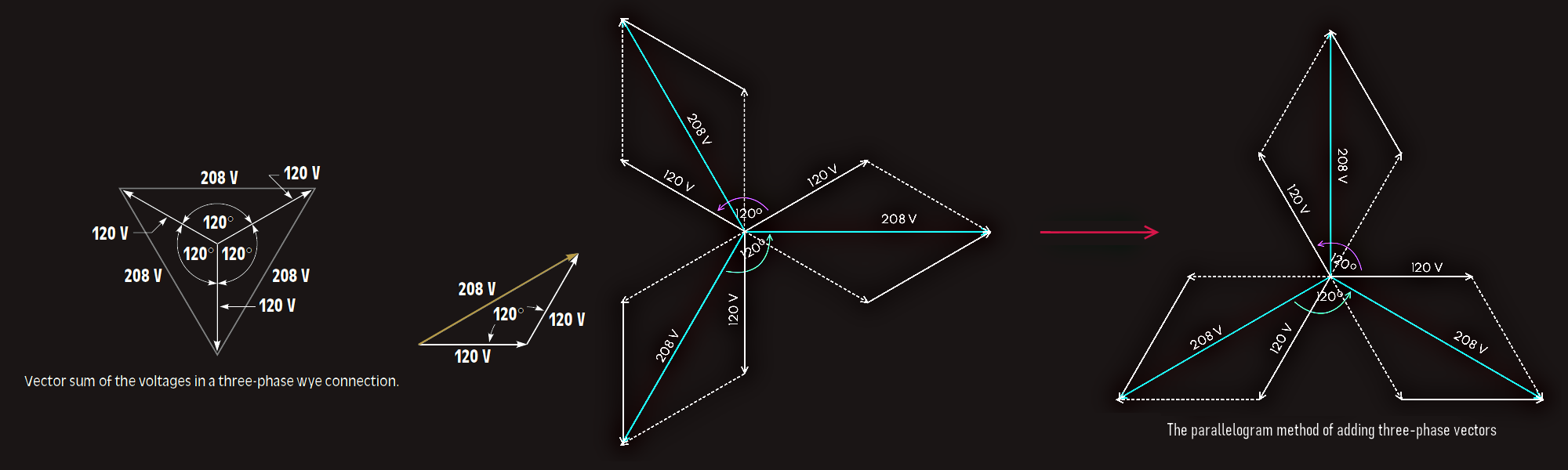
Three-phase voltages are 120° apart, not 180°. If the three voltages are drawn 120° apart, it will be seen that the vector sum of these voltages is 208 V.
Delta connection
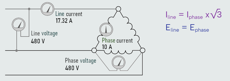
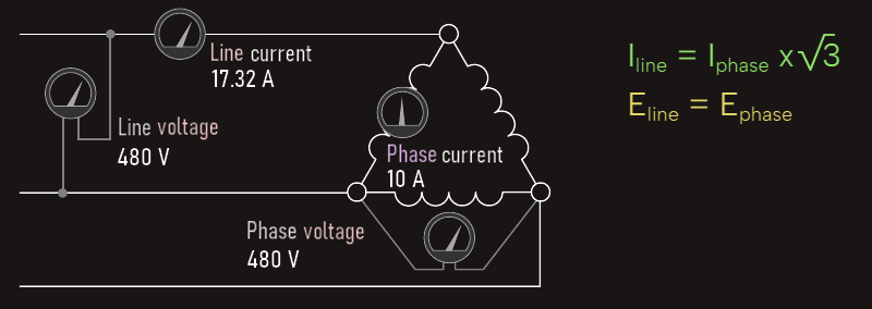
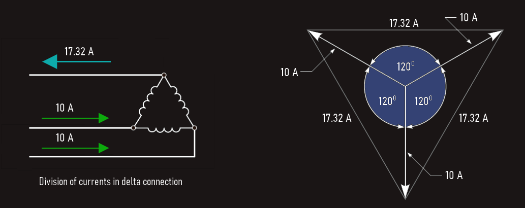
Here we have three separate inductive loads that have been connected to form a delta connection. This connection receives its name from the fact that a schematic diagram of this connection resembles the Greek letter delta (Δ). Voltmeters have been connected across the lines and across the phase. Ammeters have been connected in the line and in the phase. In the delta connection, line voltage and phase voltage are the same. The line current and phase current are different, however. The line current of a delta connection is higher than the phase current by a factor of the square root of 3 (1.732).
In the above example it is assumed that each of the phase windings has a current flow of 10 A. The current in each of the lines, however, is 17.32 A. The reason for this difference in current is that current flows through different windings at different times in a three-phase circuit. During some periods of time, current will flow between two lines only. At other times, current will flow from two lines to the third.
The delta connection is similar to a parallel connection because there is always more than one path for current flow. Since these currents are 120° out of phase with each other, vector addition must be used when finding the sum of the currents. 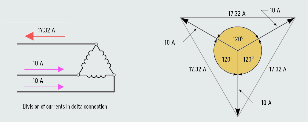
Three-phase power
There are actually two formulas that can be used when calculating three-phase power.
If line values of voltage and current are known, the power (watts) of a pure resistive load can be computed using the formula:
VA = √3 x Eline x Iline
If the phase values of voltage and current are known, the apparent power can be computed using the formula:
VA = 3 x Ephase x Iphase
So, in the first formula, the line values of voltage and current are multiplied by the square root of 3. In the second formula, the phase values of voltage and current are multiplied by 3. The first formula is used more often because it is generally more convenient to obtain line values of voltage and current, which can be measured with a voltmeter and clamp-on ammeter.
Example:
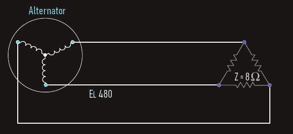
A wye-connected three-phase alternator supplies power to a delta-connected resistive load, shown on the figure below. The alternator has a line voltage of 480 V. Each resistor of the delta load has 8 Ω of resistance. Calculate another circuit values... 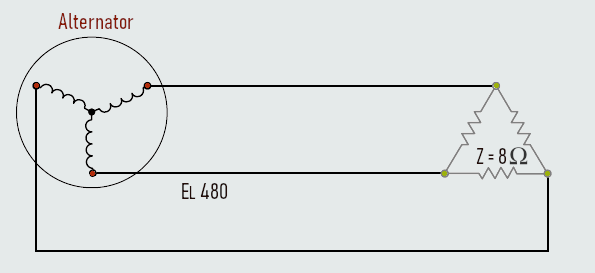
Solution:
The load is connected directly to the alternator. Therefore, the line voltage supplied by the alternator is the line voltage of the load.
EL(load) = 480 V
The three resistors of the load are connected in a delta connection. In a delta connection, the phase voltage is the same as the line voltage.
EP(load) = EL(load)
EP(load) = 480 V
Each of the three resistors in the load is one phase of the load. Now that the phase voltage is known, the amount of phase current can be computed using Ohm’s Law.
IP(load) = EP(load)/Z
IP(load) = 480/8 = 60 A
The three load resistors are connected as a delta with 60 A of current flow in each phase. The line current supplying a delta connection must be 1.732 times greater than the phase current.
IL(load) = √3 x IP(load)
IL(load) = 1.732 x 60 = 103.92 A
The alternator must supply the line current to the load or loads to which it is connected. In this example, only one load is connected to the alternator. Therefore, the line current of the load will be the same as the line current of the alternator.
IL(alt) = IL(load)
IL(alt) = 103.92 A
The phase windings of the alternator are connected in a wye connection. In a wye connection, the phase current and line current are equal. The phase current of the alternator will, therefore, be the same as the alternator line current.
IP(alt) = IL(alt)
IP(alt) = 103.92 A
The phase voltage of a wye connection is less than the line voltage by a factor of the square root of 3.
EP(alt) = EL(alt)/√3
EP(alt) = 480/√3 = 277.13 V
In this circuit, the load is pure resistive. The voltage and current are in phase with each other, which produces a unity power factor of 1. The true power in this circuit is:
P = √3 x EL(alt) x IL(alt) x PF
P = 1.732 x 480 x 103.92 x 1 = 86,394.93 W