Once the armature winding has rotated through 90° counterclockwise, and is in the vertical plane, the two perpendicular forces then exactly oppose each other, so the torque completely disappears, and the armature winding will immediately stop rotating. Even if the momentum of the armature winding is such as to cause it to rotate a little way past the vertical, there would be an immediate reversal of the two forces, resulting in a corresponding reversal in torque which would quickly return the loop back to the perpendicular position. Of course, this is an undesired effect and the armature winding should continue rotating in the same direction.
So, we can reverse the direction of the current every time the coil passes its vertical position by supplying current via a simple rotary switch, called a ‘commutator’ or, more accurately, a ‘split-ring commutator’.
One end of the armature winding is soldered or brazed to one half of the ‘split ring’, and its other end is soldered to the opposite half of the ‘split ring’. The commutator and the armature winding share the same shaft, and rotate together.
Current is fed on to, and away from, the commutator by means of a stationary pair of spring-loaded carbon brushes, which press against opposite sides of the commutator and ‘ride’ its surface as it rotates between them. As well as being a good conductor, carbon is self-lubricating – making it an ideal material from which to manufacture brushes.
We can say that the function of the split-ring commutator is to ensure that, as the armature winding of motor rotates, current always flows away from us in whichever side of the winding happens to be left of vertical, and the current always flows towards us in whichever side of the winding happens to the right of vertical. This ensures that, immediately the armature winding passes its vertical position, the current around the winding reverses direction and the armature winding will be subject to a continuous counterclockwise torque, causing it to continue to rotate in a counterclockwise direction as it passes through its vertical position. The combination of split-ring commutator and its carbon brushes is known as the motor’s ‘commutation system’. The split-ring commutator also conveniently solves the problem of how to continuously supply current to and from the coil while it is rotating.
In order to provide enough torque to drive larger mechanical loads, we need to use electromagnets, which will provide a greater flux density than permanent magnets. These are provided by field windings which are wound around the pole pieces, and form the motor’s ‘excitation system’.
At the same time, and in order to establish maximum flux density within the airgaps in which the armature rotates, those airgaps need to be as narrow as possible. This is achieved by using shaped pole pieces, which partially enclose the armature.
And finally, we need a low-reluctance magnetic circuit whose function is to guide the flux created by the excitation system to the airgaps, similar as an electric circuit, in which we use low-resistance copper wires to guide the current to some load. Because the resistance of the wire is so low, practically all the electromotive force applied to the circuit will appear across the load. Similarly, due to the low-reluctance of the magnetic circuit, practically all the magnetomotive force (m.m.f.) created by the field windings will appear across the airgaps.
Most practical d.c. motors have four or more poles, rather than just two, the armature windings are numerous, far more complex and occupy longitudinal slots that are distributed around the entire circumference of the armature and the commutator has numerous segments, not just two. These features ensure a constant torque is applied throughout the complete 360° rotation of the armature.
A motor’s starting current is always very much higher than its normal operating load current, because the armature is simply not yet rotating fast enough to generate sufficient back-e.m.f. to oppose that starting current. For larger motors, high starting currents will result in excessively high temperatures which may break down the insulation. So larger d.c. motors usually require some means of reducing their high starting currents. One method of achieving this is by inserting a variable resistor in series with the motor, and gradually lower the value of that resistance as the motor picks up speed. Such a device is called a ‘motor starter’.
Low-Pass and High-Pass Filters
Capacitors and inductors are components that impede a signal, the amount of which depends on the frequency of the signal. The capacitor delays voltage changes, and the inductor delays current changes. They are opposite in the way they react to the frequency of a signal. Capacitors block lower frequencies while letting higher ones through, whereas inductors pass lower frequencies while blocking higher ones. Let’s see what happens when we hook them up to a resistor.
Low-Pass Filters
Let's apply an AC signal to the input of RC circuit shown in figure.
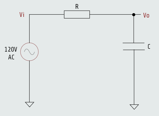
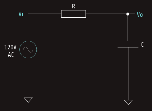
This circuit is known as a low-pass filter, and all we really need to know to understand it is the voltage-divider rule and how a capacitor reacts to frequency.
If this were a simple voltage divider, we could figure out, based on the ratio of the resistors, how much voltage would appear at the output.
At low frequencies the capacitor doesn’t pass much current, so the signal isn’t affected much. As frequency increases, the capacitor will pass more and more current, shorting the output of the resistor to ground and dividing the output voltage to smaller and smaller levels.
There is a point at which the output is half the input. It is when the frequency equals 1/2πRC.
This is known as a low-pass filter because it passes low frequencies while reducing or attenuating high frequencies.
We can make a low-pass filter with an inductor and resistor, too. Given that the inductor behaves in a way that is opposite of a capacitor, we will swap the position of the components. That’s because the inductor (being the opposite of a capacitor) passes the lower frequencies and blocks the higher frequencies. It performs the same function as the low-pass RC circuit but in a slightly different manner.
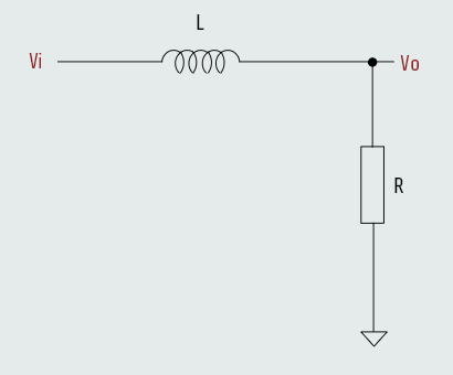
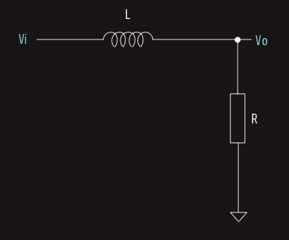
We still have a voltage-divider circuit, but instead of the resistor-to-ground changing, the input resistor is changing. At low frequencies the inductor is a short, making the ground resistor of little effect. As frequencies increase, the inductor chokes off the current, reacting in a way that makes the input element of the voltage divider seem like an increasingly large resistance. This in turn makes the resistor to ground have a much bigger say in the ratio of the voltage-divider circuit.
In conclusion; in the low-pass filter circuits, as the frequencies sweep from low to high, the capacitor starts out as an open and moves to a short while the inductor starts out as a short and becomes an open. By positioning these components in opposite locations in the voltage-divider circuit, we create the same filtering effect. The ratio of the voltage divider in both types of filters decreases the output voltage as frequencies increase. All this lets the low frequencies pass and blocks the high frequencies.
So now, let's see what might happen if we swap the position of the components in these circuits.
High-Pass Filters
Swapping the capacitor and the resistor in the low-pass circuit creates another type of circuit called a high-pass filter.
This actually means the circuit passes high frequencies while blocking low ones. The capacitor acts like a larger resistor at low frequencies, making the voltage divider knock down the output. At higher frequencies the capacitor passes more current as it becomes a short, causing a higher voltage at the output. 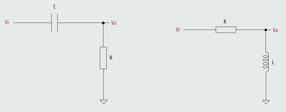
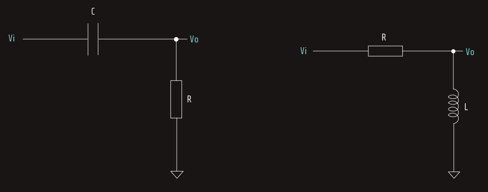 The inductor version is the inverse, circuit-wise, of the RC high-pass filter.
The half-voltage output point is also at 1/2π·τ ("tau" means time constant generically, whether referring to an RC or an RL circuit).
In conclusion; the high-pass and low-pass filters take advantage of the frequency response of either a capacitor or an inductor. This is done by combining them with a resistor to create a voltage divider that attenuates the unwanted frequencies while allowing the desired ones to pass.
Some cool things happen when we put the two reactive elements together. We can create notch- and band-pass filters where a specific band of frequencies is knocked out, or a specific band is passed while all others are blocked, and the phenomenon of resonance also occurs in what is called a tank circuit, where there is a capacitor combined with an inductor.
Let's mention that so far we have been studying passive filters. A passive component is one that is not powered externally. Being passive, these components are subject to an effect known as loading. This means that anything we hook up to the output can affect the performance of the filter.
A way to avoid this problem is to add an active component to the design, making it into an “active” filter. In adding such a component, the basic idea is to minimize this loading effect to a point that we get a nice, predictable response.
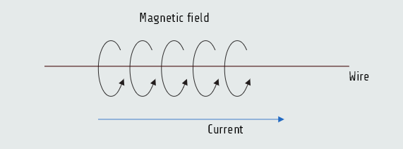
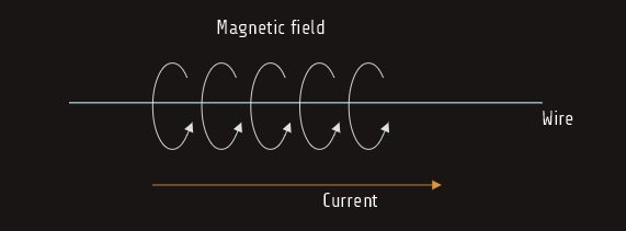
The Magnetic Field
Back in the 1820s, a man by the name of Hans Oersted noticed his compass read strangely every time he switched on a current in a wire. Eventually it was discovered that a moving electron (such as the current in a wire) creates a magnetic field perpendicular to the direction of electron movement.