


A MOSFET works similar to the BJT transistor, with one difference:
· In the BJT transistor, the current from base to emitter decides how much current can flow from collector to emitter.
· In the MOSFET transistor, the voltage between gate and source decides how much current can flow from drain to source.
To turn a MOSFET transistor on, we need a voltage between gate and source that is higher than the threshold voltage of our transistor, but not above the maximum gate-source voltage limit. How much higher depends on how much current we'd like to have flowing. The MOSFET also acts a bit like a capacitor. Once it’s charged, no more current flows through it. So when a MOSFET is on, there is no current flowing through the gate. That is, the gate-source part. When we apply a voltage between gate and source, this voltage stays there until it’s discharged. With the resistor, there is a path for the gate-source capacitor to discharge so that the transistor turns off again.
There are N-channel MOSFETs and P-channel MOSFETs - work the same way, just that the current flows in the opposite direction, and the gate to source voltage must be negative to turn it on.
When choosing MOSFET, most important are two things to have in mind:
· The gate-to-source threshold voltage. We need a voltage higher than this to turn the transistor on.
· The Continuous Drain Current. This is the maximum amount of current that can flow through the transistor.
The advantage of a transistor is that we can use a small current or voltage to control a much larger current and voltage. It is super useful when we want to control motors, high-power LEDs, speakers, relays, and more from a Raspberry Pi/Arduino/microcontroller. Sometimes we need a transistor to control the relay, also, because even the relay usually needs more current than the pin can provide; actually we use transistors in almost all electronic circuits.
Amplifiers
The transistor is also used in amplifiers. Instead of having just two states (ON/OFF) it can also be anywhere in between “fully on” and “fully off”. That means a small signal with almost no energy can control a transistor to create a much stronger copy of that signal in the collector-emitter (or drain-source) part of the transistor. The higher the input voltage, the higher the current from base to emitter. For example, we could use an amplifier to drive a speaker, illustrated below: ![]()
![]() So, the higher the input voltage, the higher the current from base to emitter, and the higher the current through the speaker. A varying input voltage makes the current in the speaker vary too, which creates sound. We would actually add a couple of more resistors to bias the transistor. Otherwise we'd get a lot of distortion.
So, the higher the input voltage, the higher the current from base to emitter, and the higher the current through the speaker. A varying input voltage makes the current in the speaker vary too, which creates sound. We would actually add a couple of more resistors to bias the transistor. Otherwise we'd get a lot of distortion.
Now, with a transistors we can build circuit elements that implement logical functions where the inputs and outputs are high and low voltages. Such components are known as logic gates. The advantage of this design is that we can alter the input to the circuit just by changing a voltage; we don’t need to flip a mechanical switch, and also the output of one circuit can easily become the input of another. Next figure on the left represents logical AND circuit with transistors: ![]()
![]() In Fig. 3. if VA and VB are high (a logical 1), then current flows through both transistors and Vout is also high (a logical 1). If VA or VB is low (a logical 0), then current doesn’t flow and Vout is also low (a logical 0).
In Fig. 3. if VA and VB are high (a logical 1), then current flows through both transistors and Vout is also high (a logical 1). If VA or VB is low (a logical 0), then current doesn’t flow and Vout is also low (a logical 0).
Figure on the far right (Fig. 4.) represents logical OR circuit with NPN transistors instead of mechanical switches.
We’ve just seen how a logic gate, a circuit that implements a logical function, can be constructed with transistors and resistors. Logic gates are available for purchase already assembled and physically packaged as a circuit component, there is no need to construct it personally with transistors, except for learning purposes. We have already made explanations about different logic gates, we will not go in detail here.
Encapsulation is a design principle when designers of a component want others to be able to easily use their creation and build upon it without needing to fully understand the details of its implementation. There is no need to know what is "inside the box", as long as the inputs and outputs continue to behave the same. Another advantage is that a team can work collaboratively on a large project, with portions of the project encapsulated. For our case, it is encapsulating transistors in a logic gate.
Once a logical statement or truth table is written, that logic can be physically implemented in hardware using logic gates. When we combine logic gates in such a way that the output is a function of the present inputs, the circuit is known as a combinational logic circuit, while sequential logic is one in which the output is a function of both present and past inputs.
Integrated circuits
Logic gates are an example of an integrated circuit. An integrated circuit (IC) contains multiple components on a single piece of silicon in a package that has external electrical contact points, or pins. ICs are also known as chips. Large numbers of miniaturized transistors and other electronic components are integrated together on the chip. This results in circuits that are orders of magnitude smaller, faster, and less expensive than those constructed of discrete components, allowing a large transistor count. The IC’s mass production capability, reliability, and building-block approach to integrated circuit design have ensured the rapid adoption of standardized ICs in place of designs using discrete transistors. ICs are now used in virtually all electronic equipment and have revolutionized the world of electronics. Each IC is designed for a specific task. The logic circuits discussed earlier that used resistors and transistors are known as resistor–transistor logic (RTL) circuits. Manufacturers built early digital logic circuits this way, but later they used other approaches, including diode–transistor logic (DTL), and transistor–transistor logic (TTL).
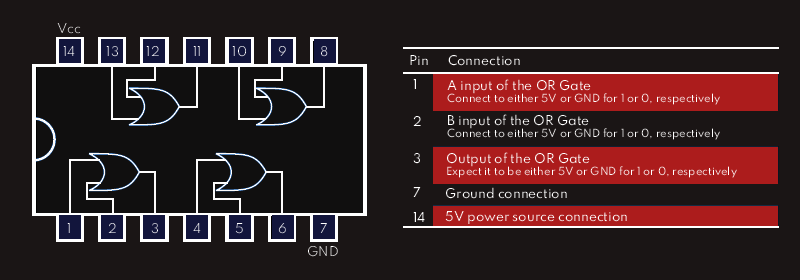
ICs that are packaged in a dual in-line package (DIP), a rectangular enclosure with two parallel rows of pins are shown below. These pins are spaced so they can easily be used on a breadboard.
Let’s say now we want to use one of the four OR gates in given chip, and we select the gate in the lower left of the pinout diagram below, connected to pins 1, 2, and 3. To use this gate, we would connect the pins as shown in the table on the right. 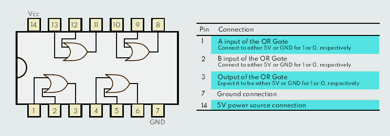
Batteries
Batteries are devices that store and release electrical energy through a chemical reaction. Battery converts the stored chemical energy into direct current (DC) electric energy. Alessandro Volta, an Italian Physicist, invented the first battery in 1800. Since then, battery technology has been experienced and used around the world. The electrochemical reaction in a battery involves transfer of electrons from one material to another (called electrodes) through an electric current. When a battery is connected to a circuit, a chemical reaction occurs between the + and – electrodes. The stored chemical energy is then generated into an electrical current.
The cell
Even though the term battery is often used, the basic electrochemical unit responsible for the actual storage of energy is called a cell. A cell is the fundamental electrochemical unit that is the source of electrical energy produced by conversion of chemical energy; it plays a major part in producing voltage and current. A cell typically contains three main components: two electrodes and electrolyte and also consists of terminals, separator and a container. Electrodes have two types, and these are the anode and cathode.
The anode is the negative electrode (also called the Fuel Electrode or the Reducing Electrode). It loses electrons to the external circuit and in the electrochemical reaction, it gets oxidized. Cathode is the positive electrode (also called the Oxidizing Electrode). It accepts electrons from the external circuit and in the electrochemical reaction, it gets reduced.
Hence, the energy conversion in a battery is due to electrochemical oxidation-reduction reaction.
The third important component of a cell is the electrolyte. An electrolyte acts as medium for transfer of charge in the form of ions between the two electrodes. Hence, the electrolyte is sometimes referred to as Ionic Conductor. An important point to be noted here that the electrolyte is not electrically conductive but it is ionic conductive.
Cells in a battery provide the necessary voltage and current levels.
Types of batteries
Electrochemical cells and batteries are categorized into two types. Although there are several other classifications, these two are the basics:
· Primary (non-rechargeable)
· Secondary (rechargeable)
Primary batteries are non-rechargeable ones. This means they cannot be recharged with electricity. The secondary batteries, in contrast, work otherwise. They are ideal for recharging in electric form.