


PLC hardware
We have different options when it comes to connecting I/O modules to the CPU. Some systems have a fixed style where the CPU comes with a fixed set of I/O points already installed and dedicated connections already determined. Other PLC systems have a stackable style where the CPU and I/O modules are separate, but come with connectors built in that are used to attach the components together. These connections form one continuous data bus throughout the system. This internal data bus is often referred to as a backplane.
Another option with PLC hardware is the modular base configuration. With this style of PLC, a separate base unit that holds the modular components is needed. Each module will seat into a slot on the base unit that is used to connect the module to the backplane already installed in the base. These bases come with different numbers of slots and some with power supplies built in. Typically, the first two leftmost slots are dedicated for the power supply and CPU. Stackable PLC components can be changed, but we have to break the backplane connection for all the modules downstream of the module we wish to remove, which could be an issue. Some of these PLCs even offer hot swapping, which means that the module change can be done with the PLC powered and with no interruption to the control process.
The I/O modules, and their respective end devices, allow the PLC to know and affect the current state of the process being controlled. There are many types of input and output modules available, but they can all be classified as:
· analog,
· discrete or
· specialty I/O.
Discrete I/O provides the PLC with ON/OFF control. Used with both AC and DC voltage ranges, they provide the CPU with a yes/no, true/false indication and allow simple full ON or full OFF responses. These input signals are provided by devices such as photoeyes, proximity switches, E-stop pushbuttons, float switches, etc. “Is the tank full?”, “Can I start this motor?”, etc.
Analog I/O deals with the gray area between full ON and full OFF that discrete I/O ignores. It provides the PLC with the data it needs for precision control of a process. Analog signals come in a variety of ranges including: 0-20mA, 4-20mA, 0-10V, etc. One important factor to remember with analog modules is the resolution they provide. The higher the resolution, the higher the accuracy of the input measurement or output response. If we want to know the exact liquid level in a tank or we want to open a valve 1/3 of the way, analog is the answer.
And specialty I/O which includes special functions like high-speed and communication. High-speed modules are needed when the input/output data is comprised of high-frequency pulses. These modules can track input data, such as encoder signals, independent of the CPU scan, guaranteeing a more accurate pulse count. And high-speed outputs can provide precision control with stepper motors used in motion or positioning applications. Communication modules provide additional communication ports/protocols that a system may require: RS232, RS485, Ethernet, etc. They can also allow a local PLC system to be expanded remotely, if needed.
The PLC power supply can be included with the base or it can be a separate unit, as mentioned earlier. They come in a variety of voltage ranges, including 12-24VDC and 110/220 VAC, and supply a limited amount of amperage. It is very important that the power supply chosen is capable of supplying the CPU and I/O modules with the power they need.
The CPU contains a microprocessor, memory storage and other integrated circuits that are used to execute the control program, store logic data, and communicate to external devices. The CPU will communicate using Ethernet, serial or USB communication ports; the protocols the CPU can support: EtherNet/IP, Modbus TCP, etc. CPU memory has expanded with the times and some CPUs today can have 50MB or more of memory available to the user. Removable memory card support is another feature that is popular today; other hardware related options available for CPUs include a battery backup, built-in I/O and status indicators/OLED message displays.
A lot of PLCs today offer plug-and-play USB connections for programming, which are fast and easy to use but require direct connections between the PC and CPU. With networked PLCs, Ethernet is typically the connection method (unless we are using a serial network) but we may want to verify if any additional communication software is required with these connections. With Web server functionality, we can access a PLC remotely using a standard Web browser and the configured IP address of our CPU. Mobile apps are also very popular and we may want to see if the PLC we are interested in has mobile capabilities.
Understanding Ladder Logic
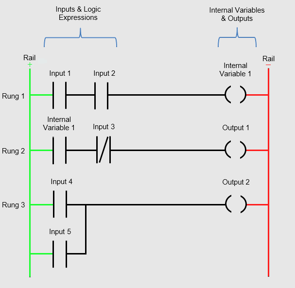
The structure behind ladder logic is based on the electrical ladder diagrams that were used with relay logic. These diagrams documented how connections between devices were made on relay panels. They are called “ladder” diagrams because they are constructed in a way that resembles a ladder with two vertical rails and rungs between them.
The positive power rail (on the left) flows to the negative power rail (on the right) through the physical devices connected on the rung.
Ladder logic was designed to have the same look and feel as ladder diagrams, but with ladder logic the physical contacts and coils are replaced with memory bits. Even though we still refer to coils and contacts in ladder logic, we should have in mind that they are memory representations, not actual devices. Physical switches and coils of relay logic are replaced with PLC’s memory location which are represented as Inputs (I) and Outputs (O).
The CPU will interpret the logic in a sequential order. Starting at the top left of the program, the CPU will work its way down the rail executing each rung or sub rung from left to right.
Once the CPU reaches the last rung it will loop back to the start of the program and run it all over. This process will continue as long as the CPU is powered and in the RUN mode. The time it takes the CPU to loop back to the beginning is known as scan time. Scan time can be important to applications where timing is critical.
The Logic behind the Ladder:
- Boolean Logic: The ON/OFF, TRUE/FALSE algebra of binary systems. The basics of which are AND, OR, and NOT operators.
- Timing: Timer instructions are available to allow for on-delayed or off-delayed events. Once triggered, the timer will turn its associated output ON (on-delay) or OFF (off-delay) after the set time has elapsed.
- Counting: Count-up and count-down functions increase or decrease the counter value on every transition of the input.
- Comparisons: Compare instructions are available to determine if values are less than, equal to, or greater than each other.
- Math: These instructions not only allow for the simple addition and subtraction but also for more complex operations like tangents, square roots, etc.
- Special functions: PID loops, communication instructions, shift registers, drum sequencers, ramp generators, etc.
PLCs from different manufacturers can be programmed in various ways:
· Relay Ladder Logic (RLL)
· Structured Text (ST) - text based programming language used to design PLC logic, it’s more like Python, Visual Basic or C.
· Function Block Diagram (FBD) - used for PLC programs which are represented in the form of graphical blocks, each function block is already pre-programed to do a certain function.
· Sequential Function Charts (SFC) - graphical representation for depicting sequential behavior of a control system, it interconnects steps, actions and transitions.
· Instruction List (IL) - low level, text based language that uses mnemonic instructions or they resemble assembly language programming.
Ladder Logic is the main programming method used for PLC’s. It mimics the relay logic (combination of switches, relays, coils and contacts). A PLC system handles many numbers representing different types of information regarding the process. These processes or machine parameters can be anything from the status of the input or output devices, timers, counters, or other data values. These memory types can be used to store a variety of information and can be used inside various Relay Ladder Logic instructions. These are commonly known as “Tags”. Tags can be of different data types: Boolean (Discrete), Integers, Floating Point, Strings, and Time.
Learning how Ladder Logic works is dependent on understanding Boolean math and logic gates. To equate this to a control circuit, let’s say Input A and Input B are the Door Open and Motion Detected inputs of a home alarm system. When wired in series, as with the AND gate, both conditions will have to be met before the alarm is activated. The door will have to be opened and the motion detector tripped before the alarm is triggered. With the OR gate, the inputs are wired in parallel and only one of the conditions is needed. In this case, the door opening or the motion detection will trigger the alarm. The option we choose is dependent on our application and on how the system is expected to perform.
A/C Motors (On/Off Control)
Most control systems have to make things move, and that usually involves motors. Lifting, pumping, robotics, conveyors, fans – pretty much everything uses a motor of some kind. General purpose three-phase AC motors are great for simple on/off systems, they are typically connected to the main power circuit with a master circuit breaker or fuses, and use contactors to enable and disable the power to the motor; overloads protect the equipment from unexpected overcurrent/overheating that can be caused by jams or breakdowns.
Motor starters
A motor starter is a combination of devices used to start, run, and stop an induction motor based on commands from an operator or a controller. The motor starter must have at least two components to operate: a contactor to open or close the flow of energy to the motor, and an overload relay to protect the motor against thermal overload.
Contactors
A contactor is a 3-pole electromechanical switch whose contacts are closed by applying voltage to a coil. When the coil is energized, the contacts are closed, and remain closed, until the coil is de-energized. The contactor is specifically designed for motor control, but can be used for other purposes such as resistive and lighting loads. Since a motor has inductance, breaking the current is more difficult, so the contactor has both a horsepower and current rating that needs to be adhered to.
Overload relays
The overload relay is a device that has three current sensing elements and protects the motor from an overcurrent. Each phase going from the contactor to the motor passes through an overload relay current-sensing element. The overload relay has a selectable current setting based on the full load amp rating of the motor. If the overload current exceeds the setting of the relay for a sufficient length of time, a set of contacts opens to protect the motor from damage.
Since the signals between the contactor and PLC are inductive, it is important to protect the control system from power surges and inductive kickback. Surge protection comes in several different types – Diode, Transorb, RC networks, depending on our application. Diodes are great if we have a DC circuit – they will offer the maximum protection but increase the time it takes to turn the motor off. Transorbs are great for AC or DC circuits, are inexpensive, and have a medium to short delay but only attenuate surges above their rated value, which can be above the threshold allowed by the PLC’s I/O. RC circuits mostly filter noise and are not much effective for true surge protection.