


Switches
LAN switches work at Layer 2, the data link layer of the OSI reference model. A switch acts like a multi-port bridge and is able to read the destination MAC address of each data packet and then forward the packet to the correct port, which means that a given device only receives those packets directed to it. Switches are hardware-based which makes them much faster when making decisions than if they were software-based. 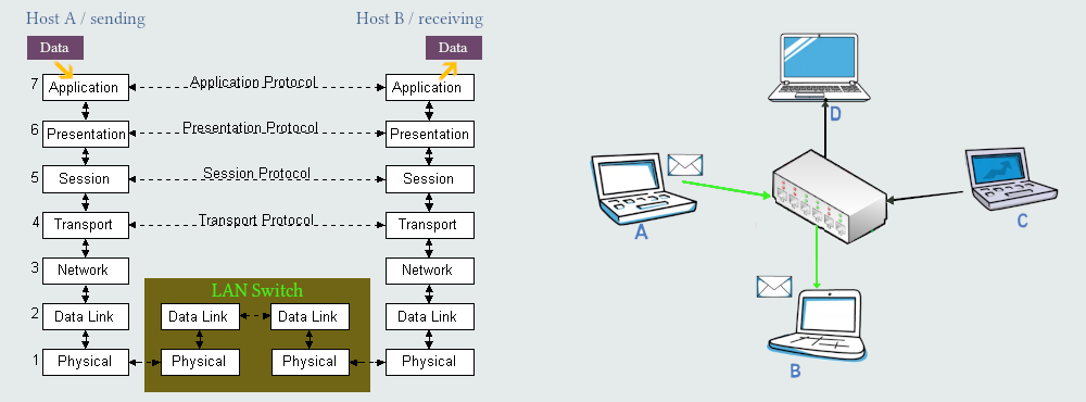
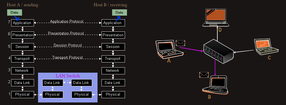 From figure above we can see that if data is sent from host A to host B, it is switched only to host B’s port, which means data can be sent from host C to host D at the same time. If two hosts simultaneously attempt to transmit to the same destination port, data is queued in the buffer and transmitted serially.
Bridges and Switches are pretty similar, both operate at the Data Link layer (Layer 2) and both can filter data so that only the appropriate segment or host receives a transmission. A network bridge connects two local area networks. A network switch, on the other hand, connects multiple clients to a network. Both filter packets based on the physical address (MAC – Media Access Control address) of the sender/receiver although newer switches sometimes include the capabilities of a router and can forward data based on IP address (operating at the Network Layer) and are referred to as IP Switches. Often the desired results could be achieved using either a switch or a bridge, but generally bridges are used to extend the distance capabilities of the network while minimizing overall traffic, and switches are used primarily for their filtering capabilities to create multiple, smaller virtual LAN’s out of one large LAN for easier management/administration (VLAN’s). Switches are also considered as superior devices than Bridges, they are hardware-based, using ASICs (Application Specific Integrated Circuits), as opposite to Bridges that are software-based; they can handle many ports, instead of only two like Bridges etc.
A hub forwards data packets to each connected computer. Assume four computers are linked to a hub, and two communicate. A hub will send data packets to all four computers. Switches, on the other hand, can determine the destination of each data packet and selectively route it to the computer that requires it. Hubs are basic networking devices that operate at the Physical Layer and they are used to send the data packets to all the connected devices, without any filtration. A Switch keeps track of the MAC addresses of all connected devices and hence, it can tell which device or system is plugged into which port. When a data packet is received, the switch understands exactly which port it should be sent to. In hub transmission, data is in the form of bits or electrical signals; in switch transmission, data is in the form of Packet (L3 Switch), or frame (L2 Switch). Hubs and switches are networking devices that generally connect multiple devices on a network, but switches offer many more advanced features and capabilities than hubs. Switches can segment a network into smaller subnets, offer faster performance and better security, and support advanced features such as VLANs, QoS, link aggregation, and PoE. While hubs may be cheaper, switches are generally a better choice for most networking applications due to their advanced capabilities and improved performance.
Switches can be either unmanaged or managed. Unmanaged switches are most often seen in small networks. They start forwarding traffic once they are turned on. Managed switches offer features to improve network performance and availability, which need to be configured by IT professionals, usually via a web browser or a SSH terminal session, and can be deployed in different topologies. A network switch will have a certain number of ports for connecting network cables, typically 24 or 48, which can be easily exceeded in a larger network. In order to allow more connections, two or more switches can be linked in a stack (stackable switch) to appear like a single, larger switch with a single control and management interface. The same result can be achieved with a modular switch with a single physical chassis, where modules can be slotted in as the demand for ports increases.
Layer 3 switches are like a collection of switches and routers in the one box. They can split physical networks into smaller pieces called VLANs using software running on the switch. A VLAN acts like an ordinary LAN, but devices do not have to be connected to the same physical segment, meaning that hosts may be located anywhere on a network and logically grouped together into the VLAN instead.
Spanning Tree Protocol (STP) is a Layer 2 network protocol used to prevent looping within a network topology. STP was created to avoid the problems that arise when computers exchange data on a local area network (LAN) that contains redundant paths. If the flow of traffic is not carefully monitored and controlled, the data can be caught in a loop that circles around network segments, affecting performance and bringing traffic to a near halt state. Networks are often configured with redundant paths when connecting network segments. Although redundancy can help protect against disaster, it can also lead to bridge or switch looping. Looping occurs when data travels from a source to a destination along redundant paths and the data begins to circle around the same paths, becoming amplified and resulting in a broadcast storm. STP can help prevent bridge looping on LANs that include redundant links. Without STP, it would be difficult to implement that redundancy and still avoid network looping. STP monitors all network links, identifies redundant connections and disables the ports that can lead to looping. In a network that contains redundant paths, bridges need to continually understand the topology of the network to control the flow of traffic and prevent looping. To do this, they exchange bridge protocol data units (BPDUs) via an extended LAN that uses a spanning tree protocol.
Power over Ethernet (PoE) is technology that passes electric power over twisted-pair Ethernet cable to powered devices (PD), such as wireless access points, IP cameras, and VoIP phones in addition to the data that cable usually carries. It enables one RJ45 cable to provide both data connection and electric power to PDs instead of having a separate cable for each. It operates between 47 and 57 volts DC. Four standards exist for providing varying amounts of power (up to 100 W) to connected devices, and some switches can be configured to provide PoE on a port-by-port basis.
Routers
Routers work at Layer 3, the network layer, of the OSI reference model. The Internet Protocol (IP) is the protocol that describes how to route messages from one computer to another computer on the network. Each message is split up into packets, and the packets hop from router to router on the way to their destination. A router makes decisions based on the IP addresses at the network layer and forwards data between different IP networks. To do this, a router needs an understanding of the routes available in the network and it stores this information in its routing table. 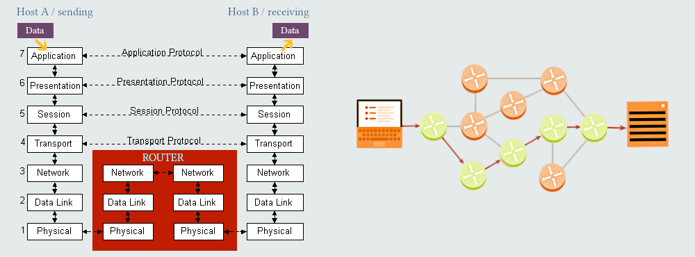
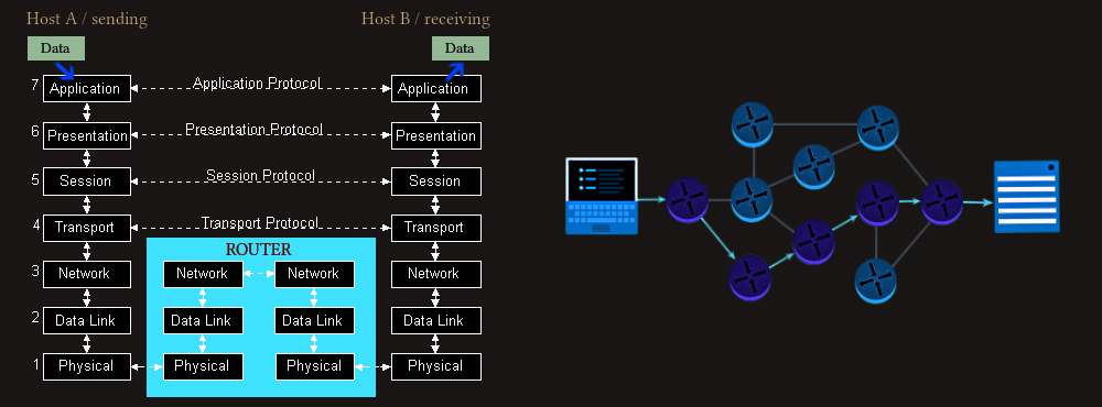 Computers send the first packet to the nearest router. When the router receives a packet, it looks at its IP header. The most important field is the destination IP address, which tells the router where the packet wants to end up. The router has multiple paths it could send a packet along, and its goal is to send the packet to a router that's closer to its final destination. The router has a forwarding table that helps it pick the next path based on the destination IP address. That table does not have a row for every possible IP address; there are 232 possible IP addresses, and that's far too much to store. Instead, the table has rows for IP address prefixes. IP addresses are hierarchical. When two IP addresses start with the same prefix, that often means they're on the same large network; router forwarding tables take advantage of that fact so that they can store far less information. Once the router locates the most specific row in the table for the destination IP address, it sends the packet along that path. If all goes well, the packet should eventually arrive at a router that knows exactly where to send it. The last router can now send the message to the destination IP address, which may be a personal computer or a server.
Routers may be statically configured with details of their neighbouring networks, and simple routers may only know about immediately adjacent neighbours, but more sophisticated routers can dynamically update in response to changes on the network using routing protocols such as RIP and OSPF. In a network linked to the internet, each host will require the IP address of the router that provides the WAN connection, i.e. the default gateway address.
Modems
Modems work at Layer 1, the physical layer. They are used to join dissimilar networks together, often a LAN to a public network such as the telephone network. There are several modem options available for WAN connection, including telephone modems and ADSL broadband modems. Voice frequency telephone modems connect to normal public telephone lines and are used for dial-up connections. They are limited in speed to 56 Kbps to avoid interfering with other conversations. Cable modems connect to the ISP using co-ax or fibre-optic cable, rather than the twisted pairs used by the public switched telephone network (PSTN) and ADSL.
Modem is short for MOdulator DEModulator. The main concept is a device that is capable of modulating, or changing, digital information into a signal which can be transmitted via some transmission medium and can then be demodulated back to its original form. In computer world, we are most familiar with the modem as an interface to the telephone line. In this case, the job of the modem is to take digital information from the computer and convert it to a signal which can be transmitted over the telephone line and decoded back by a modem on the other end.
ADSL (Asymmetric Digital Subscriber Line) is a technology that facilitates fast data transmission at a high bandwidth on existing copper wire telephone lines to homes and businesses. Unlike regular dial-up copper telephone line service, ADSL provides continuously available, always-on broadband connections. ADSL is asymmetric in that it uses most channels to transmit downstream to the user and only a small part for uploading information from the user. This is because most user applications download from the internet rather than upload. 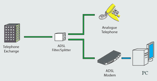
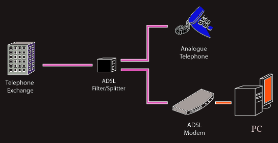 ADSL works on existing copper phone lines by using a DSL filter, or splitter, to isolate the bands with higher frequencies so that the landline and the ADSL modem can be used at the same time. At the central office, or telephone exchange, the line ends at the DSL access multiplexer (DSLAM), where an additional splitter segregates the voice signal to the phone network.