


Example:
A small indicating lamp has a rating of 2 W when connected to 120 V. The lamp must be connected to a voltage of 480 V at 60 Hz. A capacitor will be connected in series with the lamp to reduce the circuit current to the proper value. What value of capacitor will be needed to perform this job?
Solution:
The first step is to determine the amount of current the lamp will normally draw when connected to a 120-V line:
ILAMP = P/E = 2/120 = 0,0167 [A]
The next step is to determine the amount of voltage that must be dropped across the capacitor when a current of 0.01667 [A] flows through it. The capacitor reduces the current to the lamp. Since we have a series connection in this circuit, voltage dropped across resistor and voltage dropped across capacitor add in vector addition, because these two values are 90° out of phase with each other.
ET = √(ER2+EC2)
EC = √(ET2-ER2)
EC = √(4802-1202)
EC = 464,758 [V]
Now, we can find the capacitive reactance:
XC = EC/I = 464,758/0,0167 = 27.829,82 [Ω]
Since XC = 1/(2πfC),
C = 1/(2πfXC) = 1/(2x3,14x60x27.829,82)
The amount of capacitance needed to produce this capacitive reactance is 95,3 [nF]
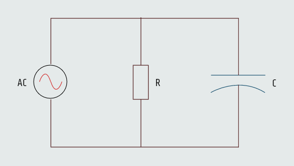
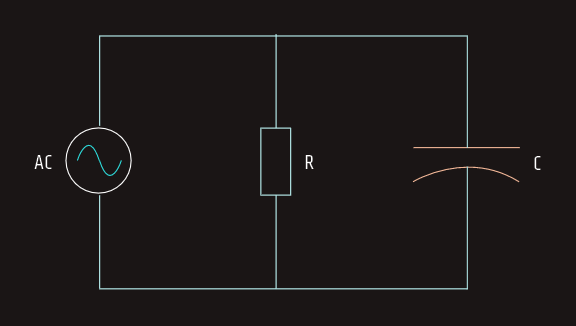
Resistive-Capacitive Parallel Circuits
Since all components connected in parallel must share the same voltage, the current flow through different components will be out of phase with each other. When resistance and capacitance are connected in parallel, the voltage across all the devices will be in phase and will have the same value. The current flow through the capacitor, however, will be 90° out of phase with the current flow through the resistor.
The amount of phase angle shift between the total circuit current and voltage is determined by the ratio of the amount of resistance to the amount of capacitance.
We will now calculate circuit values for the parallel R-C circuit where the resistance of 30 Ω is connected in parallel with a capacitive reactance of 20 Ω. The circuit is connected to a voltage of 240 VAC and a frequency of 60 Hz.
Resistive current
The amount of current flow through the resistor (IR) is:
IR = E/R = 240/30 = 8 [A]
True power
The amount of total true power (P) in the circuit can be determined by using any of the values associated with the pure resistive part of the circuit.
P = ExIR = 240x8 = 1920 [W]
Capacitive current
The amount of current flow through the capacitor (IC) is:
IC = E/XC = 240/20 = 12 [A]
Reactive power
The amount of reactive power (VARs) can be found using any of the total capacitive values.
VARs = ExIC = 240x12 = 2880
Capacitance
Capacitance value can be calculated from:
C = 1/(2πfXC) = 132,6 [µF]
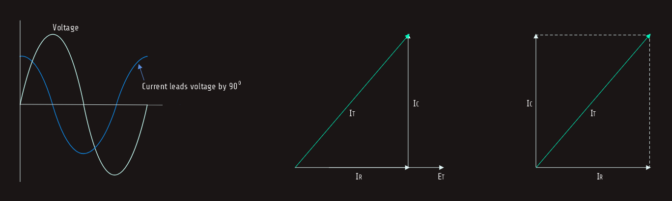
Total current
The voltage is the same across all legs of a parallel circuit. The current flow through the resistor is in phase with the voltage, and the current flow through the capacitor is leading the voltage by 90°. The 90° difference in capacitive and resistive current forms a right triangle as shown in figure below. Since these two currents are connected in parallel, vector addition can be used to find the total current flow in the circuit. 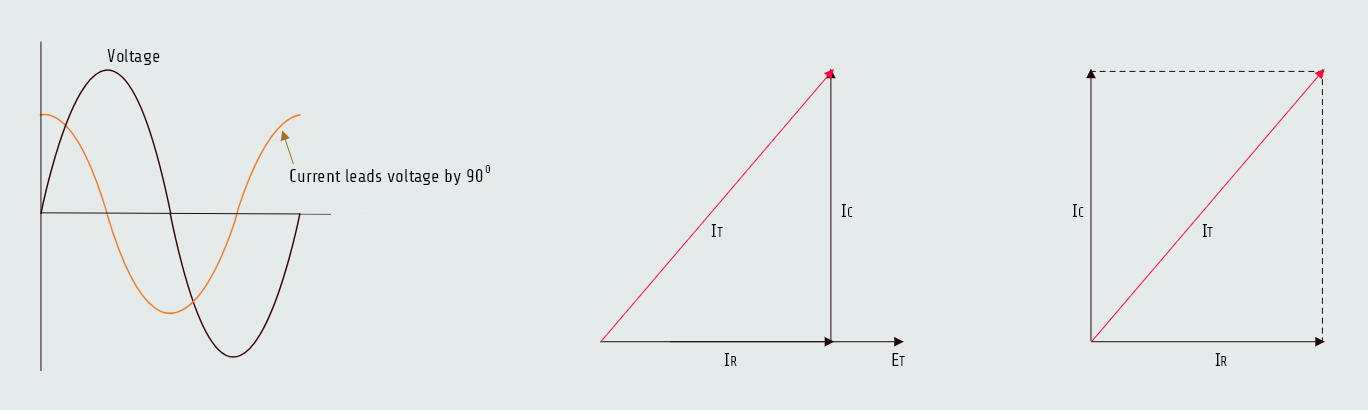
 IT = √(IR2+IC2)
IT = 14,422 [A]
Impedance
The total circuit impedance (Z) can be found by using any of the total values and substituting Z for R in an Ohm’s law formula.
Z = E/IT = 16,641 [Ω]
The impedance can also be found by adding the reciprocals of the resistance and capacitive reactance. Since the resistance and capacitive reactance are 90° out of phase with each other, vector addition must be used:
Z = 1/√((1/R)2+(1/XC)2)
Apparent power
The apparent power (VA) can be computed by:
VA = ExIT = 240x14,422 = 3461,28
Power factor
The power factor (PF) is the ratio of true power to apparent power:
PF = W/VA x 100 = 55,47 %
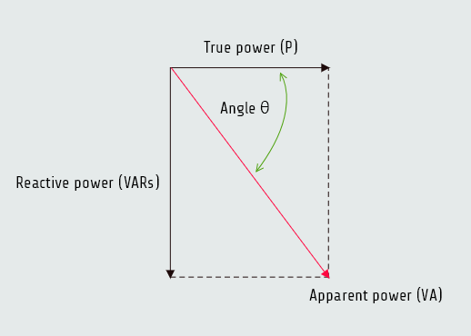
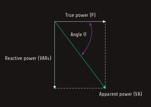
Angle Theta
The cosine of angle theta is equal to power factor:
cos(∠ θ) = PF
cos(∠ θ) = 0,5547
∠ θ = 56,310
Angle theta is the angle developed between the apparent and true power.
R-L-C AC circuits
RLC series circuit
When an AC circuit contains elements of resistance, inductance, and capacitance connected in series, the current is the same through all components, but the voltages dropped across the elements are out of phase with each other. The voltage dropped across the resistance is in phase with the current; the voltage dropped across the inductor leads the current by 90° and the voltage dropped across the capacitor lags the current by 90°.
The ratio of resistance, inductance, and capacitance determines how much the applied voltage leads or lags the circuit current. If the circuit contains more inductive VARs than capacitive VARs, the current lags the applied voltage and the power factor is a lagging power factor. If there are more capacitive VARs than inductive VARs, the current leads the voltage and the power factor is a leading power factor.
Inductive reactance and capacitive reactance are 180° out of phase with each other, so they cancel each other in an AC circuit. This cancellation can permit the impedance of the circuit to become less than either or both of the reactances, producing a high amount of current flow through the circuit. When Ohm’s law is applied to the circuit values, the voltage drops developed across these components can be higher than the applied voltage.