


The resistance of any material depends upon the following factors: its length (symbol: l), its cross-sectional area (symbol: A) and its resistivity (symbol: ρ, pronounced ‘rho’).
Length
The resistance of a material is directly proportional to its length.
In other words, doubling the length of a conductor will double its resistance, while halving its length will halve its resistance, etc.
Area
The resistance of a material is also inversely proportional to its cross-sectional area. In other words, doubling its cross-sectional area will halve its resistance, while halving its cross-sectional area will double its resistance, etc.
The area of a circle is proportional to the square of its diameter. So doubling the diameter of a circular-section wire, will actually quadruple its cross-sectional area and, therefore, reduce its resistance to a quarter. For the same reason, halving the diameter of a wire will quarter its cross-sectional area and quadruple its resistance.
Resistivity
Knowing how the length and cross-sectional area affects resistance, we can now express these relationships, mathematically, as follows: R~l/A.
We can change proportion sign (~) with an equals sign (=) by inserting a constant of proportionality:
R = constant x (l/A)
This constant is called the resistivity (symbol: ρ, pronounced ‘rho’) of the material. So, the final equation for resistance becomes:
R = ρ x (l/A)
R - resistance (ohms, Ω)
ρ - resistivity (ohm metres, Ωm)
l - length (metres, m)
A - cross-sectional area (square metres, m2)
We can make an analogy of resistance by thinking about heavy box that we drag across the floor. A force called friction resists the movement of the box. The friction dissipates the energy loss in the system with heat, so friction makes things get warm. The function of a resistor in electrical circuit is equal to friction.
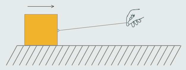
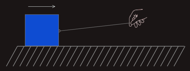
The resistor resists the flow of electricity just like friction resists the speed of the box, and it heats up, also. An equation called Ohm's Law describe this relationship: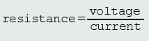

The problem with resistance is that it depends not only on the material from which a conductor is made, but also on the physical dimensions of that conductor. If we were to increase the length of a conductor, then the measured resistance would also increase; if we were to increase the cross-sectional area of the conductor, then the measured resistance would decrease.
Resistivity allows us to compare different materials’ abilities to pass electrical current that is independent from these geometrical factors.
Resistivity is a physical property of a material, which varies from material to material, and is affected by temperature. Accordingly, values of resistivity are always quoted at a particular temperature – usually, 293 K (20oC).
Resistivity is defined as ‘the resistance of a unit length of a substance with a uniform cross-section’.
Resistivity, then, is a fundamental property of a material that describes how easily that material can allow the passage of an electrical current. High values of resistivity imply that the material is very resistant to current; low values of resistivity imply that the material allows current to pass very easily.
In fact, materials are classified as being a ‘conductor’, an ‘insulator’ or a ‘semiconductor’ (semiconductors are materials used in the manufacture of electronic components, such as diodes and transistors) according to its range of resistivities.
The resistivity of insulators is not necessarily constant for a particular temperature, as it is with conductors. Instead, it generally varies considerably according (amongst other things) to the insulator’s purity, its surface condition and the duration of the application of a potential difference. Furthermore the resistivity of most insulators decreases with an increase in temperature.
The enormous differences between the resistivities of insulators and conductors result in massive differences in their values of resistance.
For example; sample of mica (insulator), just 25 mm long, has the same resistance as a copper conductor, having the same cross-sectional area, but measuring a staggering 14 290 000 000 000 000 kilometres long!
The reciprocal of resistivity is called ‘conductivity’, which is measured in siemens per metre (S/m).
As we have learned, the resistance of a metal conductor is inversely proportional to the cross-sectional area of that conductor – i.e. the lower the cross-sectional area, the greater the resulting resistance.
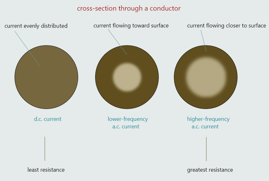
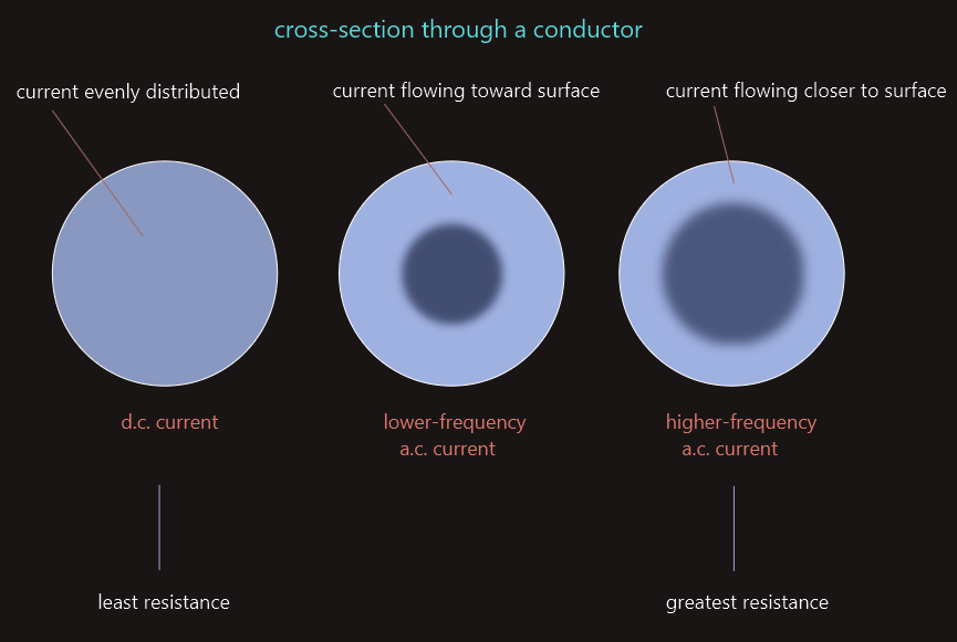
For direct current, the charge carriers are distributed uniformly across the cross-section of the conductor.
However, this isn’t the case with alternating current. For an alternating current, the charge carriers tend to travel closer to the surface of the conductor – known as the ‘skin effect’.
The ‘skin effect’ becomes increasingly pronounced at higher frequencies – at higher frequencies, the charge carriers tend to drift even closer to the surface of the conductor, reducing the effective cross-sectional area even more.
The effect of the ‘skin effect’, therefore, is to reduce the effective cross-sectional area of a conductor, thus increasing the resistance of the conductor. The resistance of a conductor to alternating current is somewhat higher than it would be to direct current, and we call this higher value its ‘a.c. resistance’ to distinguish it from its resistance to direct current. ‘A.C. resistance’ should not be confused with another form of opposition to a.c. current, called ‘reactance’.
At normal mains frequency (50/60 Hz), the difference between a.c. and d.c. resistance is slight, but it increases significantly at higher frequencies.
In fact, at radio frequencies (300 MHz–300 GHz), the skin effect is so pronounced that there is little point in using solid conductors, so tubes (called ‘waveguides’) are used instead.
The resistance of the insulating material surrounding a conductor can be expressed with the same equation: R~l/A.
As there is no such thing as a perfect insulator, a tiny current (in the order of microamperes), called a leakage current, passes through the insulation from the conductor to the surroundings (earth, or adjacent conductors). So, in this context, the ‘length’ (l) of the insulation corresponds to its thickness (i.e. the path through which the leakage current passes), and the ‘area’ (A) of the insulation is the product of the average circumference of the insulation and the length of the conductor.
As the thickness of the insulation and the circumference of any given conductor are fixed values then, for any given cable, its resistance: R~1/length of conductor.
The insulation resistance is inversely proportional to the length of the insulated conductor – i.e. if we were to, say, double the length of the conductor, then its insulation resistance will be halved.
Resistance will vary with temperature because, as we have learned, a material’s resistivity is affected by temperature.
It is quite possible to calculate the resistance of a material at any temperature but some general rules for pure-metal conductors, insulators, carbon, and certain alloys are:
• Pure metal conductors - an increase in temperature of a pure metal conductor will cause its resistance to increase.
• Insulators and carbon - an increase in temperature of an insulator, and of carbon (a conductor) will cause their resistance to decrease.
• Alloys - certain alloys, such as constantan (copper with 10–55% nickel) are manufactured so that an increase in temperature has very little effect upon their resistance.
So, variations in temperature can affect the physical properties of any material – including, amongst others, its optical, electrical and magnetic properties.
One of the physical properties of a material is its resistivity and, since resistance is directly proportional to resistivity, any change in resistivity will result in a change in resistance. The way in which a material’s resistivity and, therefore, resistance changes depends upon the nature of the material itself.
Pure metal conductorsIn the case of pure metal conductors, such as copper or aluminium, an increase in temperature will cause an increase in its resistance. Conversely, reducing the temperature of a pure metal conductor will cause its resistance to fall. The amount of change in resistance for a given change in temperature, varies from metal to metal. |
AlloysSome alloys, such as constantan (a copper-nickel alloy), have been specially developed to maintain a fixed resistance over a wide range of temperature variations. Such alloys are used in the manufacture of measuring instruments, for example, where any change in resistance due to temperature variations can affect the accuracy of such instruments. |
InsulatorsIn the case of an insulator, an increase in temperature causes a corresponding increase in the internal energy of its atoms which cause free electrons to be liberated to act as additional charge carriers, effectively reducing its resistance. If the temperature is allowed to increase, then it will eventually lead to a complete breakdown of the insulator’s ability to withstand voltage. High temperatures are a major cause of insulation breakdown, which is why it is important never to interfere with the ventilation provided with electrical equipment. |
CarbonCarbon is widely used in the manufacture of contacts used to connect the stationary and rotating conductors of electrical motors and generators. These contacts are termed ‘brushes’. Carbon is ideal for this application because it is selflubricating and is a relatively good conductor. It is a special case because, unlike most other conductors, its resistivity decreases when its temperature increases. In other words, it behaves in the opposite way to metal conductors. |
General equation that applies to a temperature coefficient of resistance quoted at any temperature is R2 = R1(1+αT1(T2-T1)).
R2 - resistance at temperature T2
R1 - resistance at temperature T1
αT1 - temp coefficient of resistance, quoted at temperature T1
T2 - upper temperature
T1 - lower temperature (ambient)
Most commonly, however, the coefficient is quoted at an ambient temperature of 20ºC – in which case, we can replace T1 with 20°C, the equation becomes R2 = R20(1+α20(T2-20)).
If, however, the coefficient is quotated (less commonly) at zero-degrees Celsius, then the equation becomes R2 = R0(1+α0(T2-0)), which actually is R2 = R0(1+α0T2).
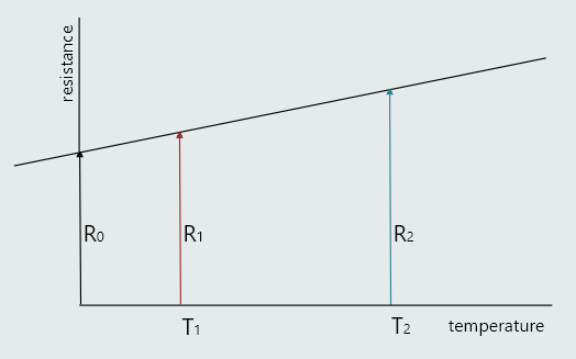
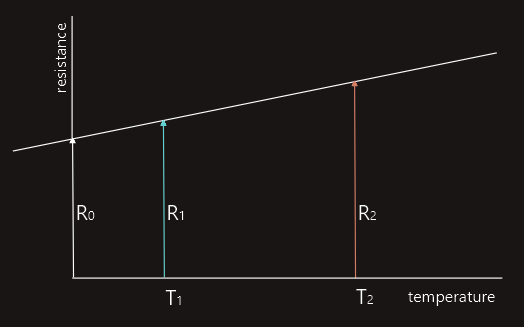
In the resistance/temperature graph shown on the left, resistance is found using equation:
R1 = R0(1+α0T1)
R2 = R0(1+α0T2)
If we now divide second by first equation, we get:
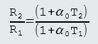
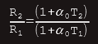
R2 - final resistance
R1 - initial resistance
T2 - final temperature
T1 - initial temperature
α0 - temp coefficient at 00C