


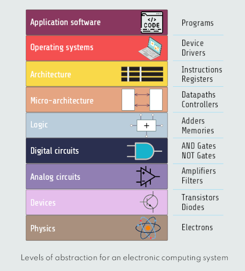
At the lowest level of abstraction is the physics, the motion of electrons. Our system is constructed from electronic devices such as transistors (or vacuum tubes, before). These devices have well-defined connection points called terminals and can be modeled by the relationship between voltage and current as measured at each terminal. By abstracting to this Device Level, we can ignore the individual electrons. The next level of abstraction is analog circuits, in which devices are assembled to create components such as amplifiers. Analog circuits input and output a continuous range of voltages. Digital circuits such as logic gates restrict the voltages to discrete ranges, which we will use to indicate 0 and 1. In logic design, we build more complex structures, such as adders or memories, from digital circuits. Microarchitecture links the logic and architecture levels of abstraction. The architecture level of abstraction describes a computer from the programmer’s perspective. For example, the Intel x86 architecture is defined by a set of instructions and registers (memory for temporarily storing variables) that the programmer is allowed to use. Microarchitecture involves combining logic elements to execute the instructions defined by the architecture. A particular architecture can be implemented by one of many different microarchitectures with different price and performance. Going further, the operating system handles low-level details such as accessing a hard drive or managing memory. Finally, the application software uses these facilities provided by the operating system to solve a problem for the user.
Now that we’ve established that high and low voltages represent 1 and 0 in our digital circuit, let’s consider how we can build a digital circuit. We want a circuit where the input and output voltages are always a predetermined high or low value, or at least within an allowable range. To help us accomplish this, let’s bring in a circuit element called a mechanical switch. A switch is useful because it’s digital in nature. It’s on or off. When the switch is on, it acts like a simple copper wire through which current flows freely. When the switch is off, it acts like an open circuit and no current can flow. With a switch we can construct logical operators like AND, OR, etc., that we already have described earlier.
However, in computing devices, we can’t practically use mechanical switches. The inputs to a computer are numerous, and flipping switches to control those inputs isn’t a great design. Also, computing devices need to connect multiple logical circuits together — the output of one circuit needs to become the input of another. To accomplish this, our switches need to be electrically, rather than mechanically, controlled. Fortunately, there’s a circuit component that can act as an electronic switch: the transistor.
How transistors work
We’ll focus here on the two most common transistors: BJT and MOSFET.
The transistor works like an electronic switch. It can turn a current ON and OFF. A simple way to think about it is to look at the transistor as a relay without any moving parts. A transistor is similar to a relay in the sense that we can use it to turn something ON and OFF. We should mention that a transistor can also be turned partly on, which is useful for building amplifiers.
A relay is an electromechanical switch. It works in the same way as a manual switch, but instead of having to manually push the switch, we apply power to it to change the switch position. It is very useful for turning the power of a device on and off automatically, and for switching higher power devices with a low power. So, a relay consists of an electromagnet and a mechanical switch. ![]()
![]()
An electromagnet is a simple device made up of a wire wound in a coil around a core of ferromagnetic material such as iron. When a wire conducts current, it produces a magnetic field. If we wind a wire into a coil around a core of ferromagnetic material such as iron, we magnify this field and we get an electromagnet with enough magnetism to do various things that we also have described in previous explanations.
The relay also consists of a mechanical switch; when the electromagnet is powered, it will break the initial connection between two pins and create a new connection between the one from previous connection and the new one pin. On many relays there are at least two switches inside so that we can switch two devices at once.
BJT (Bipolar Junction Transistor) transistors
BJTs have three terminals: base, collector, and emitter. There are two types of BJTs: NPN and PNP. The two differ in the way they respond to the application of current to the base terminal. For our purposes, we focus on NPN BJTs. ![]()
![]() In an NPN transistor, applying a small current at the base allows a larger current to flow from the collector to the emitter. In other words, if we think of the transistor as a switch, then applying current at the base is like turning the transistor on, and removing that current turns the transistor off.
In an NPN transistor, applying a small current at the base allows a larger current to flow from the collector to the emitter. In other words, if we think of the transistor as a switch, then applying current at the base is like turning the transistor on, and removing that current turns the transistor off.
There is a connection between the sizes of the two currents that is called the gain of the transistor, and for a general-purpose transistor, this could be around 100. This means that for 0.1 mA flowing from the base to the emitter, we can have 10mA flowing from collector to emitter.
Let’s look at how a transistor can be wired as an electronic switch, showed on the figure below: ![]()
![]() The NPN transistor is the most common of the Bipolar Junction Transistors (BJT). But there is another one called a PNP transistor that works the same way, just that all the currents are in the opposite direction.
The NPN transistor is the most common of the Bipolar Junction Transistors (BJT). But there is another one called a PNP transistor that works the same way, just that all the currents are in the opposite direction.
MOSFET transistors
The MOSFET transistor is another very common type of transistor; it also has three pins: Gate (g), Source (s), Drain (d). ![]()
![]()