Electric Power System Basics
High-Voltage Transmission Lines
Electric energy is transported across the countryside with high-voltage lines because the line losses are much smaller than with low-voltage lines. The advantage of high-voltage transmission is that less current is required to produce the same amount of power. The reduction of current permits smaller wires to be used, which results in a savings of material. We want the smallest amount of current that we can use to deliver the power to consumers. All wires currently used have some resistance. Let's say that total resistance of the transmission line leading from a power station to our local substation is R. Furthermore, local community demands a power P from that substation, P = U·I.
This means that current is I = P/U, and higher the transmission line voltage, the smaller the current.
The line loss is given by Ploss = I2R = P2R/U2.
We mentioned above that P is fixed (constant) by community demand and R is as small as we can make it (using appropriate conductor cables, of appropriate cross-section, big cables), then line loss decreases strongly with increasing voltage.
Loss fraction Ploss/P = P·R/U2 increases with increasing P; power transmission is less efficient at the times of higher demand. Again, this is because power is proportional to current but line loss is proportional to current squared. Line loss can be quite large over long distances and line loss power goes into heating the transmission line cable which, per meter length, isn't very much heat.
Fundamentals of electric power
Energy
Energy is the ability to perform work. Energy cannot be created or destroyed, but can be converted from one form to another. For example, chemical energy in fossil fuels can be converted into electrical energy and electrical energy can be converted into useful work in the form of heat, light and motion. Energy, in electric power industry, is measured in watt-hours (Wh), or for larger values is expressed in kWh, MWh, GWh, while scientific community measures energy in joules (J), watt-seconds.
Voltage
Voltage is measured between two points and is a measure of the capacity of a device connected to those points to perform work per unit of charge that flows between those points. Voltage can be considered analogous to the pressure in a water pipe. Voltage is measured in volts (V), and for large values in kV, MV.
Current
Current is a measure of the rate of flow of charge through a conductor; it can be considered analogous to the rate of flow of water through a pipe. Current is measured in amperes (A). Current can be unidirectional (direct current - DC) or it can periodically reverse directions with time (alternating current - AC). Voltage can also be unipolar (one point is always at a higher voltage - potential than the other, DC voltage) or alternating in polarity with time, AC voltage.
Alternating currents and voltages in power systems have nearly sinusoidal profiles. AC voltage and current waveforms are defined by three parameters:
- · amplitude
- · frequency
- · phase
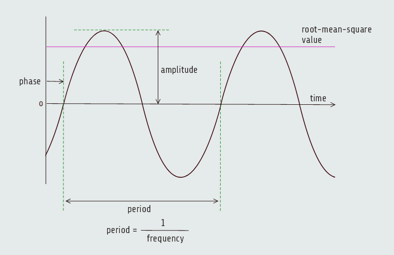
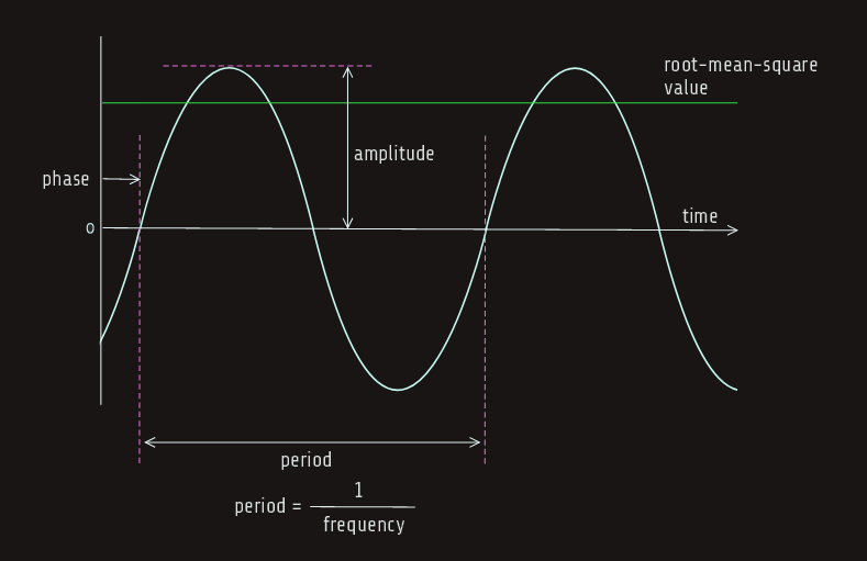
RMS value of the voltage is the equivalent DC voltage with the capacity to perform the same amount of work.
In the case of AC, the amplitude is equal to the rms value multiplied by the square root of two. So, the amplitude of the AC voltage in a 120 V outlet is 170 V, and 120 V refers to the rms value, 170 = 120 √2.
In the case of DC, the amplitude and rms values are the same.
Frequency is the rate at which current and voltage in the system oscillate, or reverse direction and return. Frequency is measured in cycles per second, also called "hertz" (Hz). In the U.S., as well as the rest of North America and parts of South America and Japan, the ac system frequency is 60 Hz, while in the rest of the world it is 50 Hz.
DC can be considered a special case of AC with the frequency equal to zero.
The time in seconds it takes for an ac waveform to complete one cycle is called the "period", it is inverse of frequency.
The phase of an ac waveform is a measure of when the waveform crosses zero relative to some established time reference. Phase is expressed as a fraction of the ac cycle and measured in degrees (ranging from -1800 to 1800). In dc system, there is no concept of phase.
AC is preferred in electric power systems; it allows voltage levels to be changed with ease using a transformer. The voltage level of a DC system can also be changed, but doing so requires more sophisticated and expensive equipment using power electronics technology. DC can be advantageous when energy has to be transmitted over long distances, dc is used also to connect ac systems that operate at different frequencies or systems with identical frequencies that are not synchronized.
We already know that impedance is a property of a conducting device that represents the impediment to the flow of current through it. Impedance actually has two components: resistance and reactance. Resistance causes energy loss in the conductor as moving charges collide with the conductor's atoms and results in electrical energy being converted into heat. Resistance increases with length and decreases with increasing conductor cross-sectional area, it does not introduce any phase shift between voltage and current. Voltages and currents create electric and magnetic fields, respectively, in which energy is stored. Reactance is a measure of the impediment to the flow of power caused by the creation of these fields. If we are talking about energy stored in magnetic fields, we will say that element has inductive reactance, and when talking about energy stored in electric fields, element has capacitive reactance. The presence of reactance in a system creates a phase shift between voltage and current; reactance is a function of frequency, also. We have already learned formulas for inductive and capacitive reactance, dependent of frequency; inductive reactance increases with frequency while capacitive ractance decreases with frequency. Inductive reactance causes the current to lag the voltage (a negative phase shift, the current is "busy" storing energy in a magnetic field as the voltage proceeds), while capacitive reactance forces the current to lead the voltage (a positive phase shift, the voltage is "busy" storing energy in an electric field as the current proceeds).
The impedance of a transmission line is primarily comprised of inductive reactance; its current will be out of phase with and lags its voltage - to compensate for this, elements with capacitive reactance (capacitors) are connected to the transmission line. The positive phase shift caused by these capacitors cancels out the negative shift due to the inductive reactance of the transmission line and forces the transmission voltage and current to be in phase, which is a good thing.
Power
Power is the rate at which energy is flowing or the work is being done. We know by now that voltage is the amount of work done for each unit of charge that flows and current is the rate of flow of charge, so the product of voltage and current is the rate of work - power, instantaneous power, more precisely. Since power loss is Ploss = I2·R, loss in a transmission line can be reduced by increasing the transmission voltage, which allows the current to be reduced for the same amount of power transmitted, and current reduced means significant reduce in power loss.
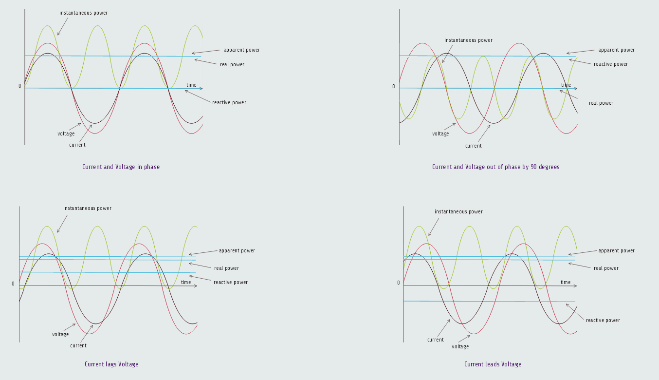
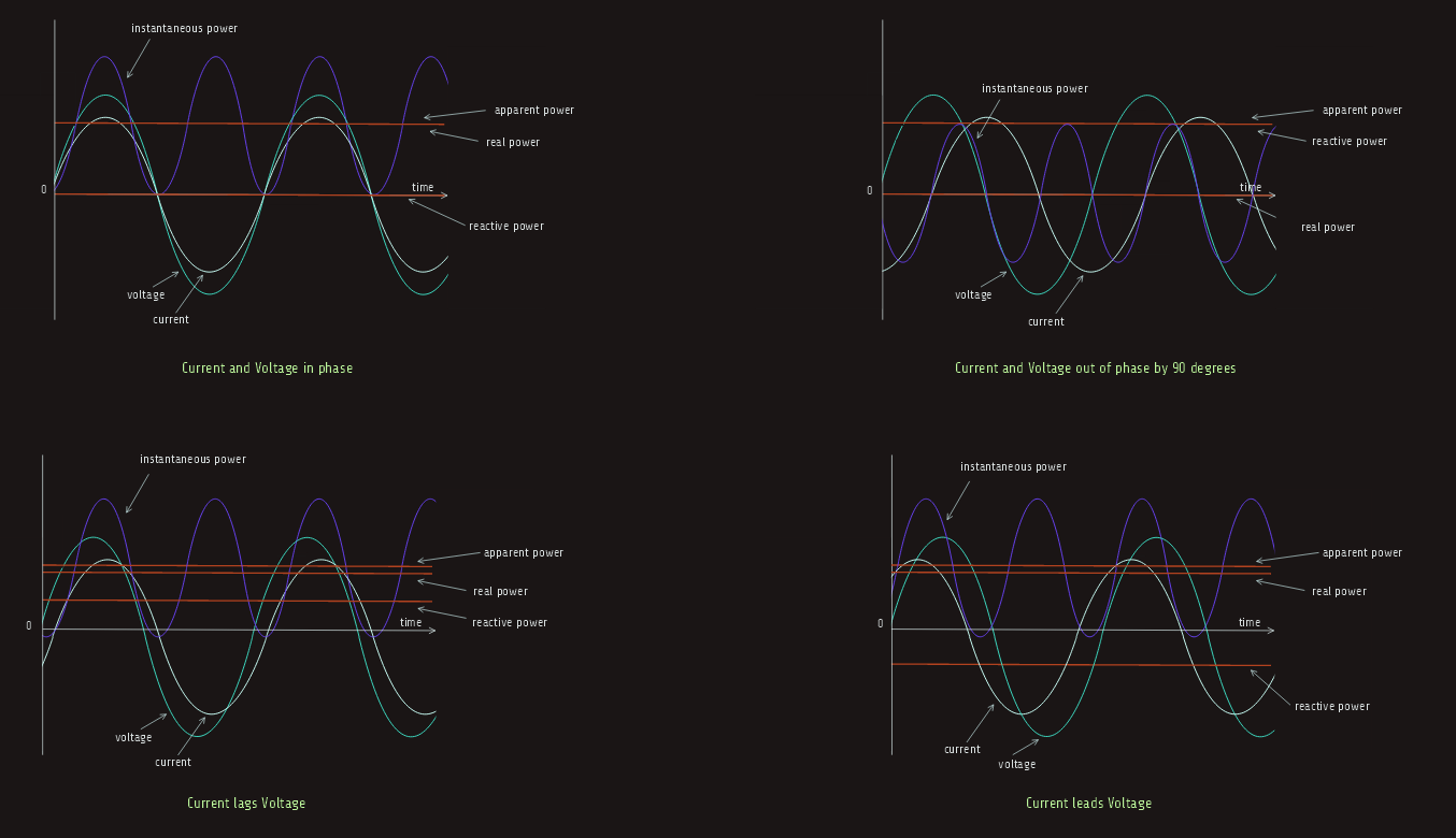
In ac systems where voltage and current oscillate many times a second, the instantaneous power they produce is also rapidly varying, so it is more valuable to have measures of power that are averages over many cycles. These measures are real power, reactive power and apparent power. Apparent power can be determined from real and reactive power, which are two independent measures of power.
Real power or "active power" or "average power" is the average value of instantaneous power and it is the power that actually does work. It is measured in watts. Although instantaneous power can be flowing in both directions, real power only flows in one direction.
P = UIcos∠φ (∠φ = 900 → P = 0).
If the voltage and current waveforms are in phase, then instantaneous power, although varying, is always positive and flows in one direction. In this case, all the power is real power. However, if we have out of phase condition, then power takes on both positive and negative values and in addition to the real power that is flowing in one direction, there is back and forth movement of "reactive power". Reactive power is measured in VARs. While it does no useful work, reactive power flow still causes power losses in the system because current is flowing through components, such as transformers and transmission lines, which have resistance (reactance). Reactive power can be positive or negative, but unlike instantaneous power, its sign doesn't indicate the direction of reactive power flow. Instead, the sign simply indicates the relative phase shift between current and voltage. When current lags voltage due to the presence of inductive reactance, reactive power is positive; when current leads voltage due to the presence of capacitive reactance, reactive power is negative.
Apparent power is the product of rms voltage and rms current, and is always greater than or equal to real and reactive power. Apparent power is measured in volt amperes (VA). The ratio of real power to apparent power is called "power factor"; utilities like to maintain unity power factor as it implies that all of the power that is flowing is doing useful work. Electrical equipment, such as transformers and transmission lines, must be thermally rated for the apparent power they process.